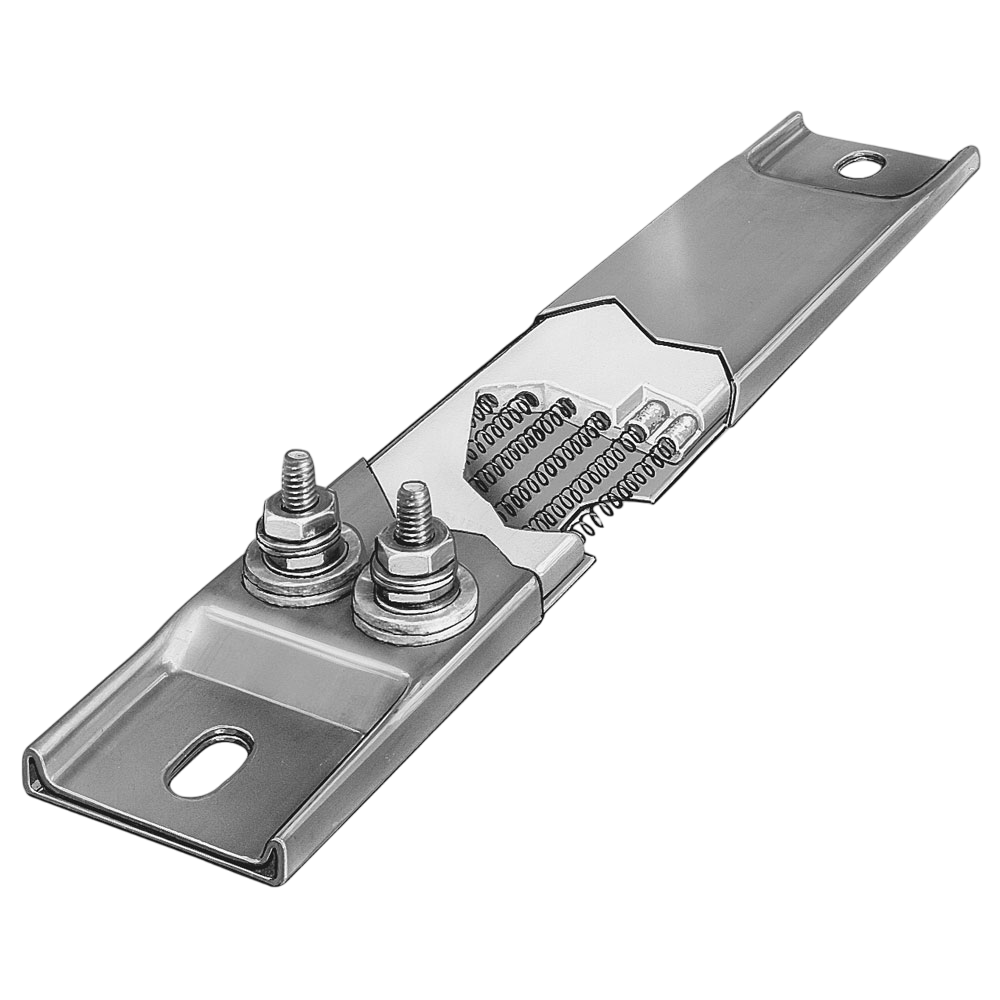
Type 304 Stainless Steel sheath provides physical strength and resistance to high temperatures of up to 1200°F (650°C) and chemical corrosion. Helically wound resistance wire coil made from nickel-chrome wire is evenly stretched and precisely strung through the ceramic insulator, providing uniform heat. A custom mixture of several high purity magnesium oxide grain sizes, chosen to increase thermal conductivity and dielectric strength, are used to fill all remaining space inside and around the ceramic insulator. Channel strip heaters are available with or without mounting tabs. If without, the ends are silver soldered shut to prevent moisture and contaminants from entering the heater.
No options available for this section based on your selections
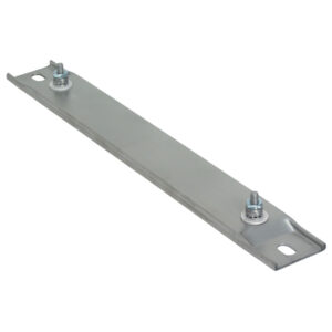
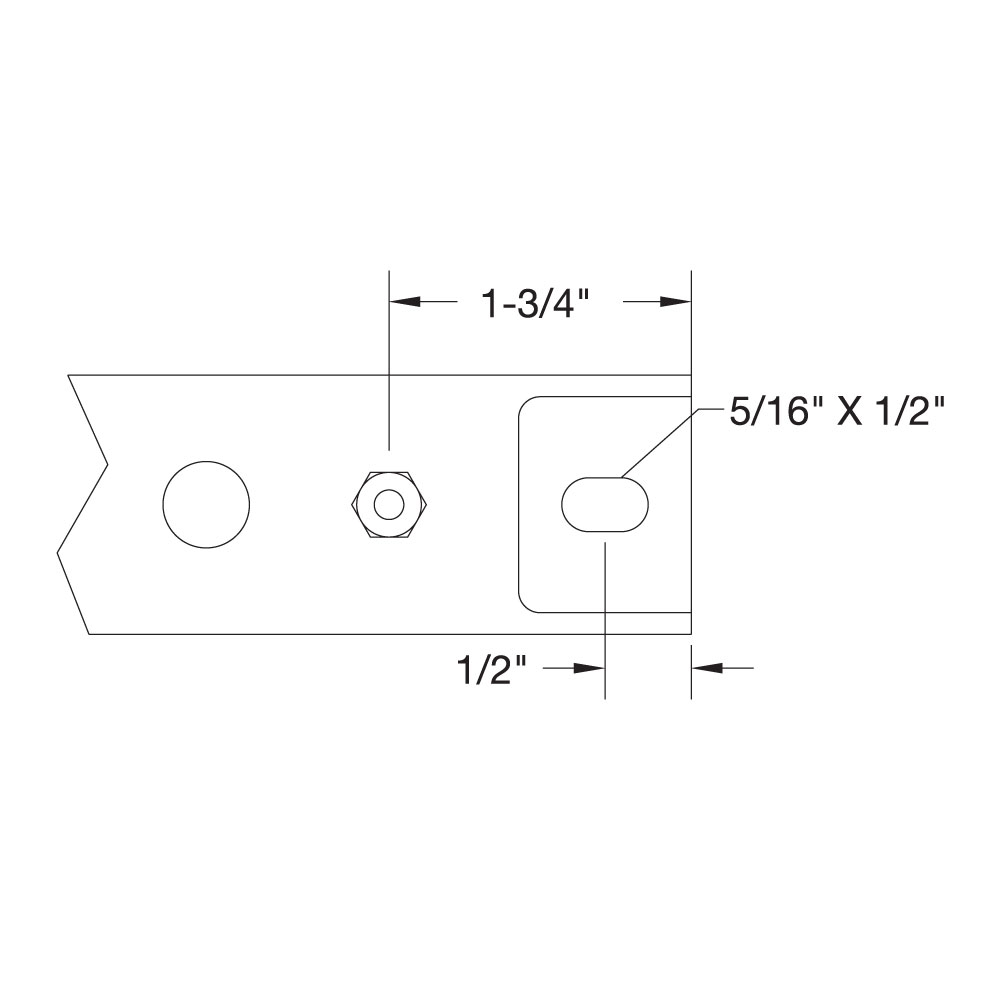
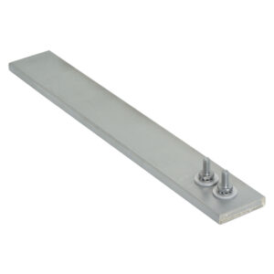
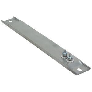
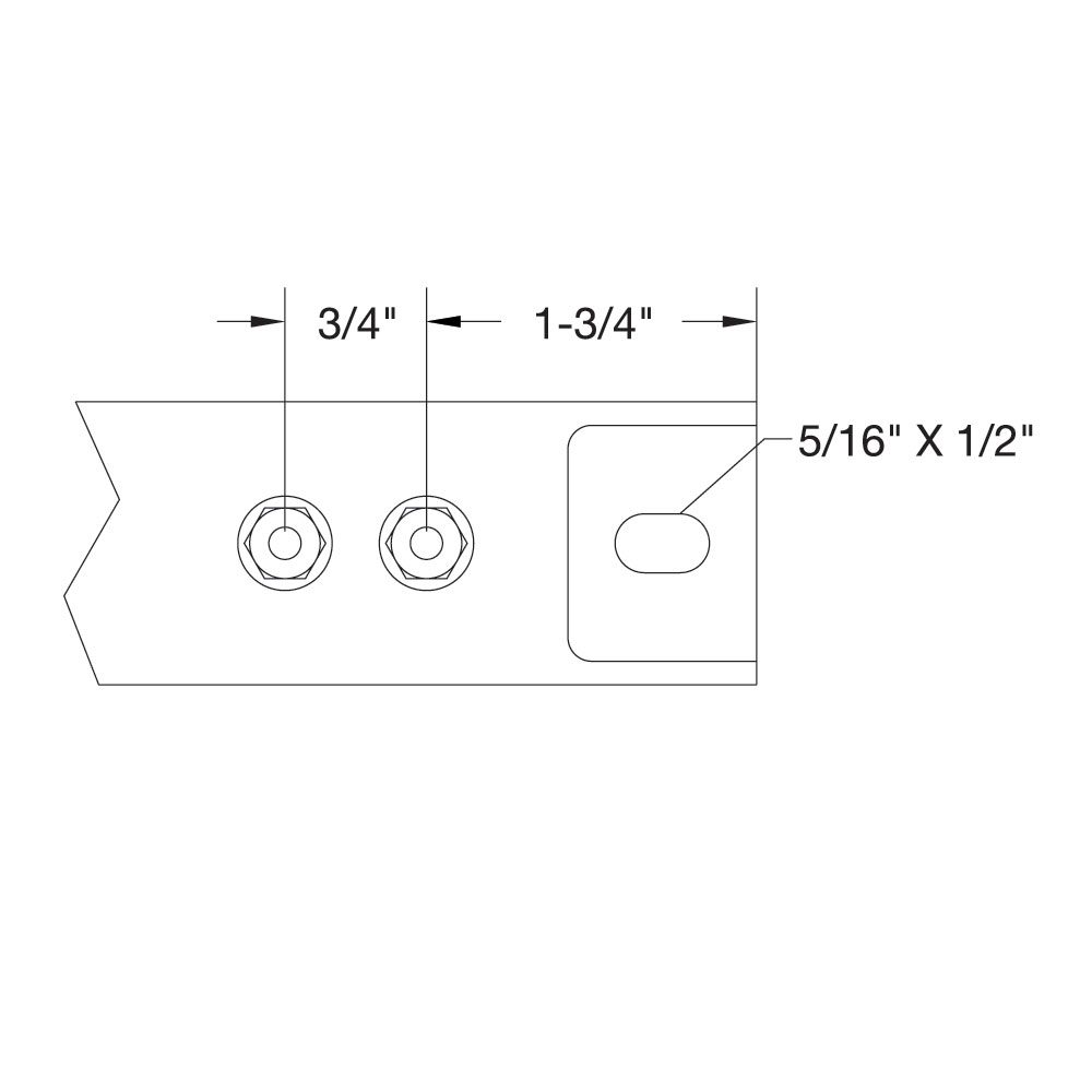
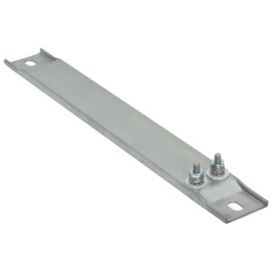
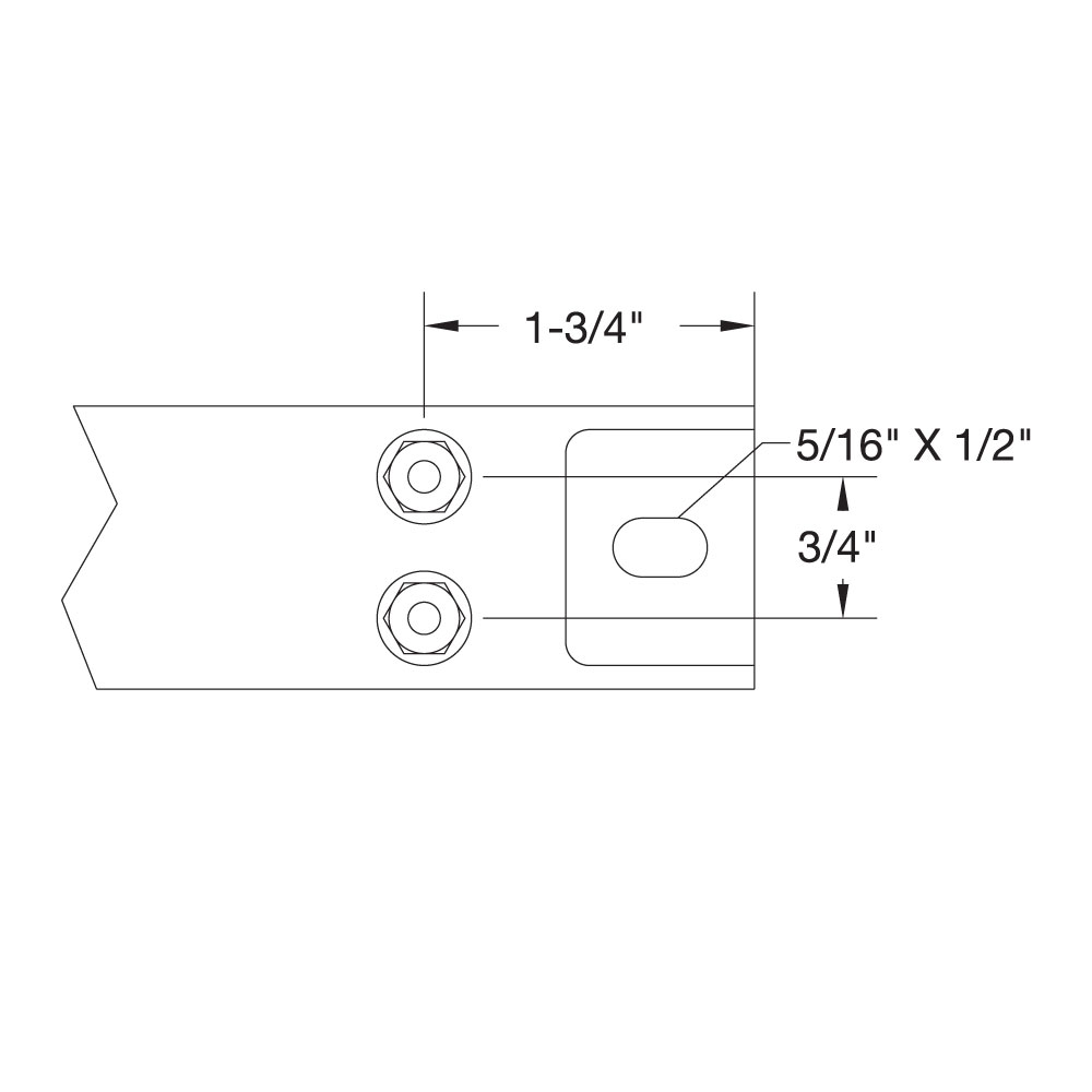
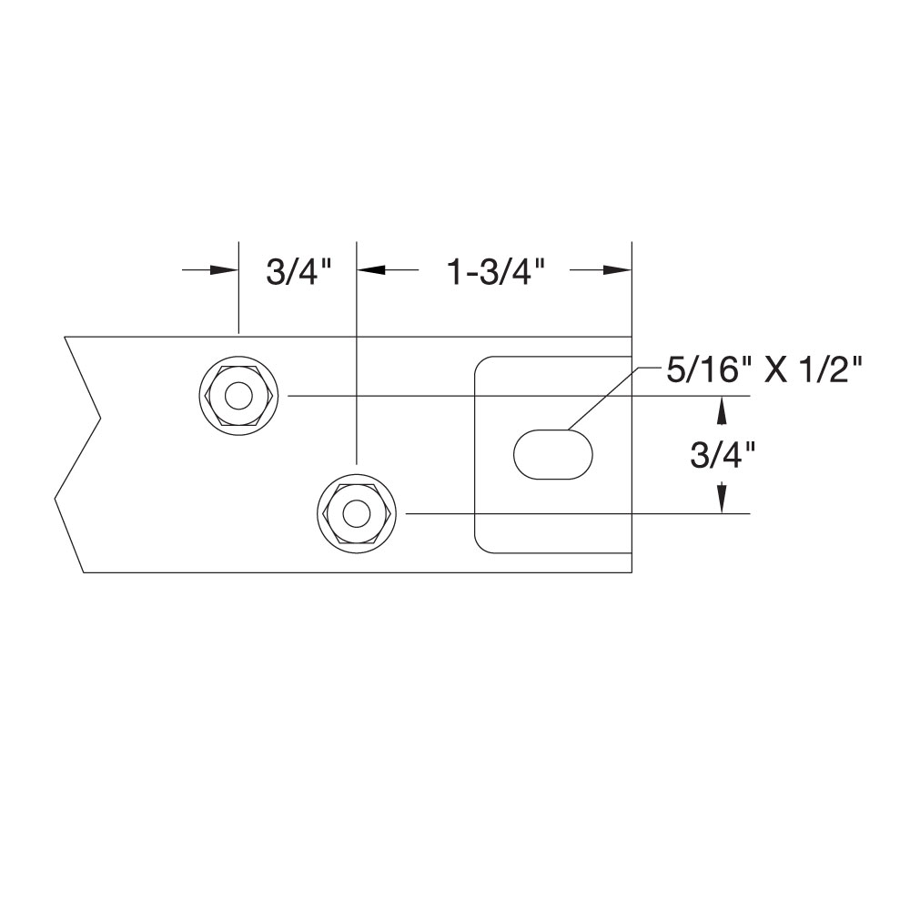
Channel Strip Heater With Mounting Tabs
Heaters are available with mounting tabs. When supported by mounting tabs, the terminal end should be secured firmly. Opposite end should be loose to allow for thermal expansion. Mounting Slot Size Standard 5/16″ × 1/2″ Special Bushings 1/2″ × 5/8″
Heaters are available with mounting tabs. When supported by mounting tabs, the terminal end should be secured firmly. Opposite end should be loose to allow for thermal expansion. Mounting Slot Size Standard 5/16″ × 1/2″ Special Bushings 1/2″ × 5/8″
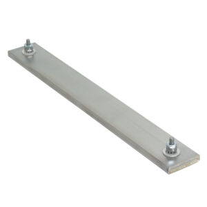
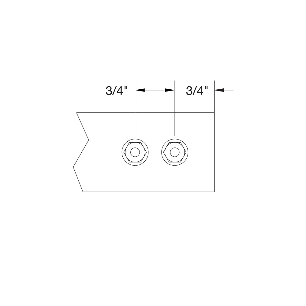
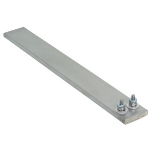
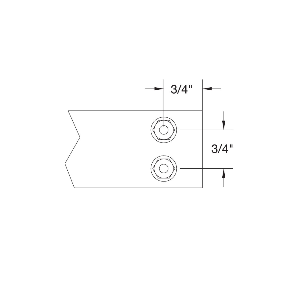
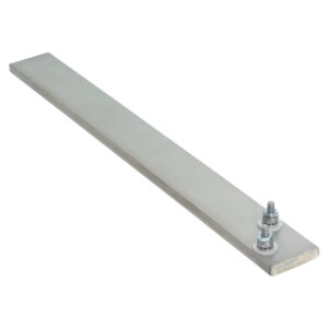
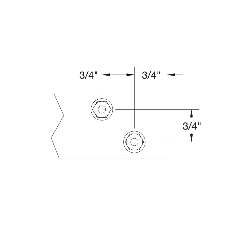
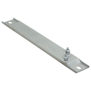
Channel Strip Heater Without Mounting Tabs
Heaters without mounting tabs have ends that are silver soldered shut to prevent moisture and contaminants from entering the heater. For surface mounting installations, Channel Strip heaters must be securely clamped along their entire length to a smooth metal surface.
Heaters without mounting tabs have ends that are silver soldered shut to prevent moisture and contaminants from entering the heater. For surface mounting installations, Channel Strip heaters must be securely clamped along their entire length to a smooth metal surface.
Electrical Terminations
No options available for this section based on your selections
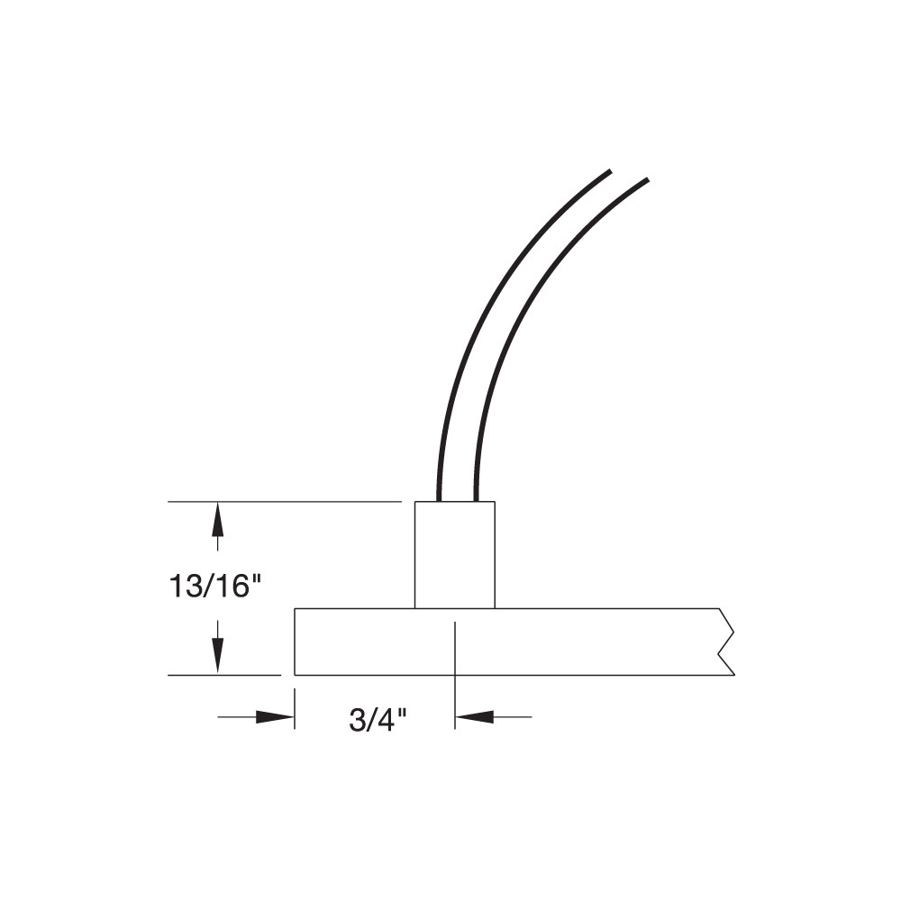
Type L1: Flexible Lead Wires at Top
Flexible lead wires exit from top of heater. 10″ long leads standard; if longer leads are required, specify.
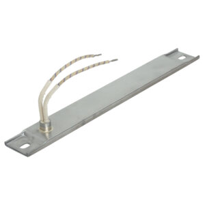
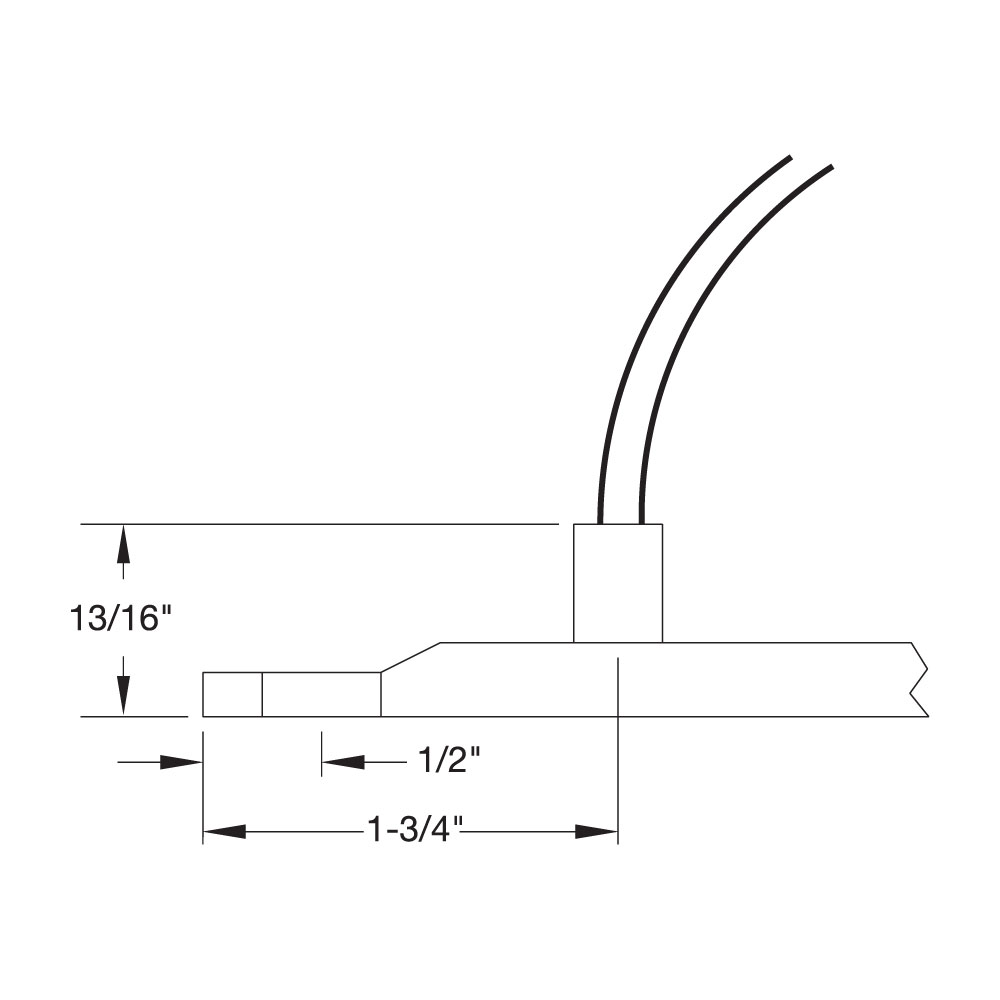
Type L1: Flexible Lead Wires at Top with Mounting Tabs
Flexible lead wires exit from top of heater. 10″ long leads standard; if longer leads are required, specify.
Maximum Amps: 10 at 240VAC
Maximum Volts: 480
with mounting tabs
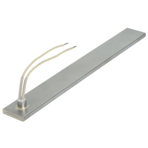
Type L: Flexible Lead Wires at Heater End
Flexible lead wires exit from end of heater. 10″ long leads standard; if longer leads are required, specify. Recommended only for tight quarters or where flexibility of the lead wire is required.
Flexible lead wires exit from end of heater. 10″ long leads standard; if longer leads are required, specify. Recommended only for tight quarters or where flexibility of the lead wire is required.
Maximum Amps: 10 at 240VAC
Maximum Volts: 480
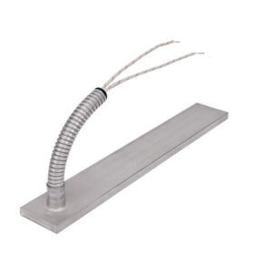
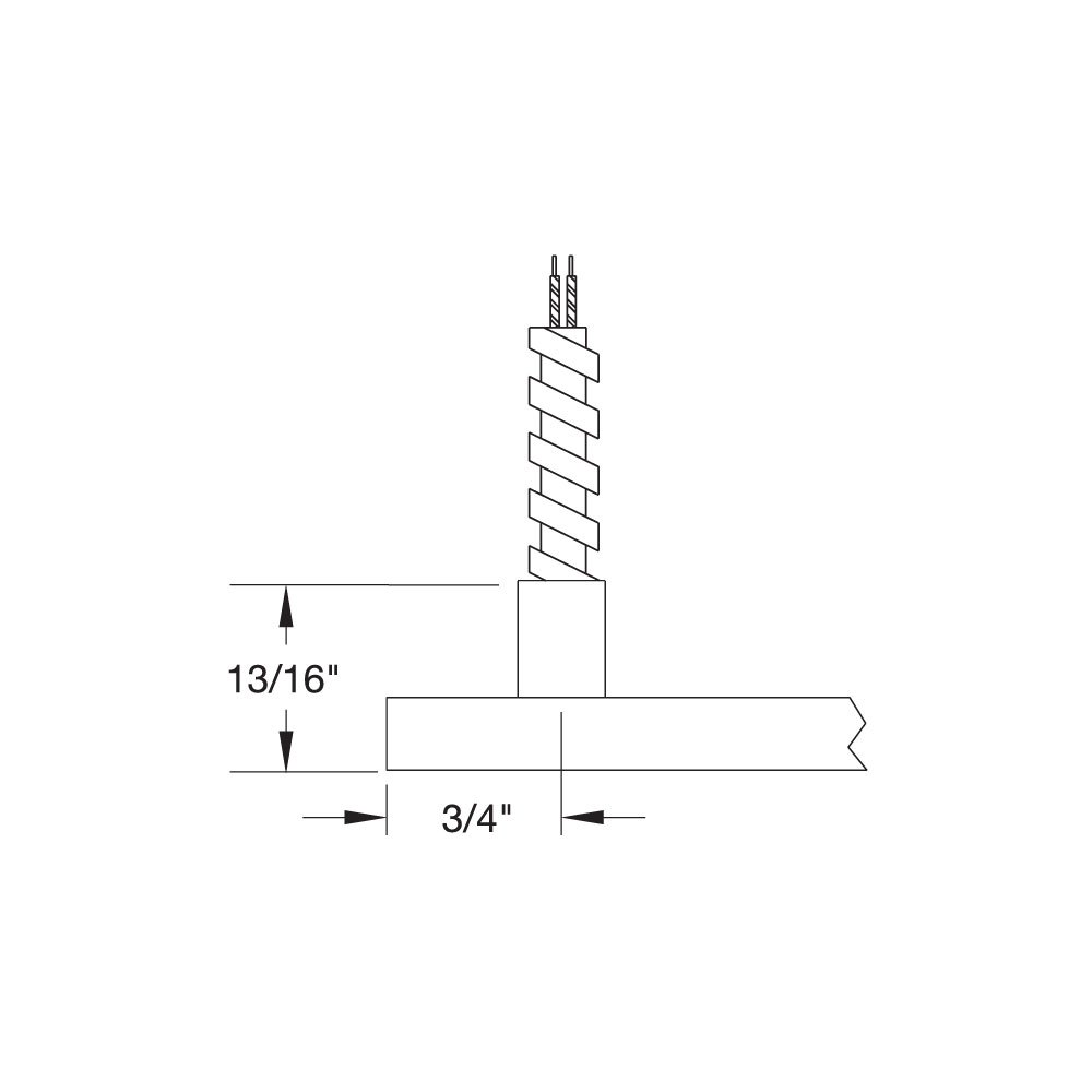
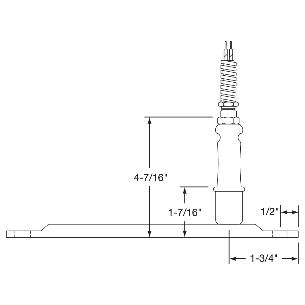
Type R1: Armor Cable at Top
Armor cable provides strength and prevents contamination from getting into the heater. 10″ of armor over 12″ long leads are standard; if longer leads or armor are required, please specify.
Armor cable provides strength and prevents contamination from getting into the heater. 10″ of armor over 12″ long leads are standard; if longer leads or armor are required, please specify.
Maximum Amps: 10 at 240VA
Maximum Volts: 480
Type R1A: Galvanized cable Type R1B: Stainless steel cable
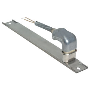
Type R1: Armor Cable at Top with Mounting Tabs
Armor cable provides strength and prevents contamination from getting into the heater. 10″ of armor over 12″ long leads are standard; if longer leads or armor are required, please specify.
Armor cable provides strength and prevents contamination from getting into the heater. 10″ of armor over 12″ long leads are standard; if longer leads or armor are required, please specify.
Maximum Amps: 10 at 240VA
Maximum Volts: 480
Type R1A: Galvanized cable Type R1B: Stainless steel cable
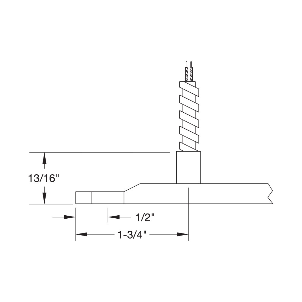
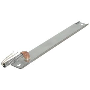
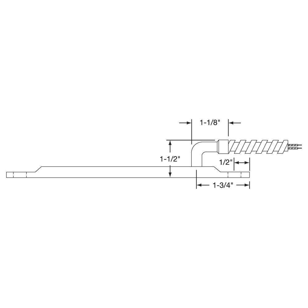
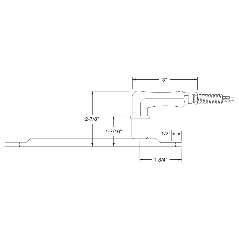
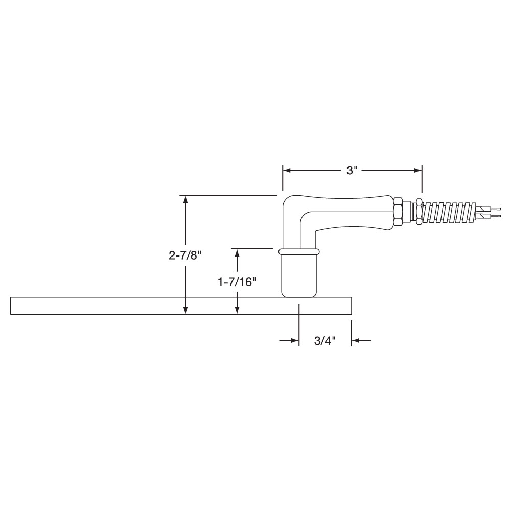
Type R2: Right-Angle Armor Cable at Top
Right-angle armor cable prevents contamination from getting into the heater. 10″ of armor over 12″ long leads is standard; if longer leads or armor are required, please specify.
Right-angle armor cable prevents contamination from getting into the heater. 10″ of armor over 12″ long leads is standard; if longer leads or armor are required, please specify.
Maximum Amps: 10 at 240VAC
Maximum Volts: 480
Type R2A: Galvanized cable Type R2B: Stainless steel cable Type R2C: Elbow and leads only (no cable)
Type R2: Right-Angle Armor Cable at Top with Mounting Tabs
Right-angle armor cable prevents contamination from getting into the heater. 10″ of armor over 12″ long leads is standard; if longer leads or armor are required, please specify.
Type R2: Right-Angle Armor Cable at Top with Mounting Tabs
Right-angle armor cable prevents contamination from getting into the heater. 10″ of armor over 12″ long leads is standard; if longer leads or armor are required, please specify.
Maximum Amps: 10 at 240VAC
Maximum Volts: 480
Type R2A: Galvanized cable Type R2B: Stainless steel cable Type R2C: Elbow and leads only (no cable)
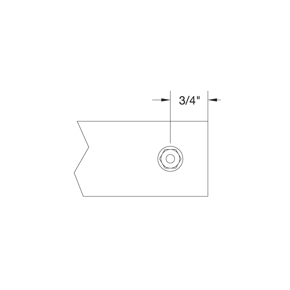
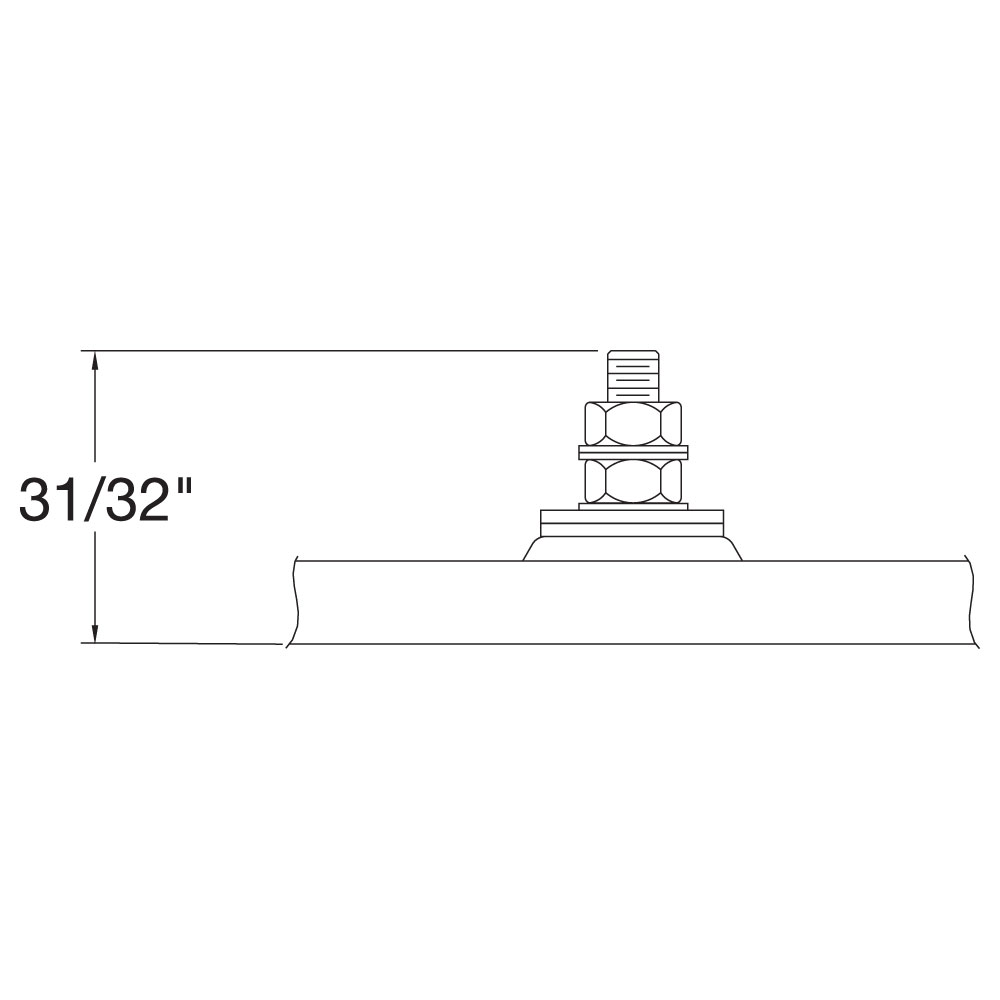
Type T4: Screw Terminals at one end with Mounting Tabs
10-32 Screw Terminals offset (Diagonal) at one end
With Mounting Tabs10-32 Screw Terminal Height
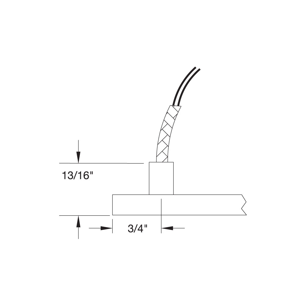
Type W1: Wire Braid at Top
Wire braid provides strength and protection to the lead wire insulation, offering sharp bending not possible with armor cable. 10″ of wire braid over 12″ long leads is standard; if longer leads or braid are required, specify.
Wire braid provides strength and protection to the lead wire insulation, offering sharp bending not possible with armor cable. 10″ of wire braid over 12″ long leads is standard; if longer leads or braid are required, specify.
Maximum Amps: 10 at 240VAC
Maximum Volts: 480
No Mounting Tabs
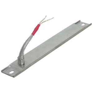
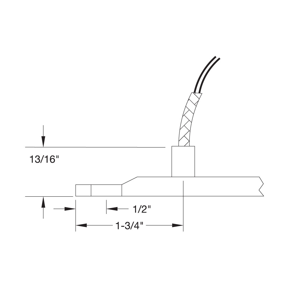
Type W1: Wire Braid at Top with Mounting Tabs
Wire braid provides strength and protection to the lead wire insulation, offering sharp bending not possible with armor cable. 10″ of wire braid over 12″ long leads is standard; if longer leads or braid are required, specify.
Wire braid provides strength and protection to the lead wire insulation, offering sharp bending not possible with armor cable. 10″ of wire braid over 12″ long leads is standard; if longer leads or braid are required, specify.
Maximum Amps: 10 at 240VAC
Maximum Volts: 480
With Mounting Tabs
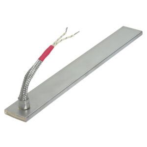
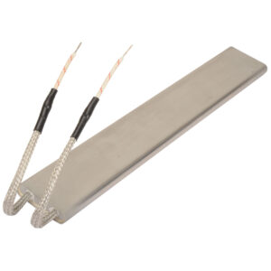
Type W2: Wire Braid at Heater End
Stainless steel braid over each lead wire offers sharp bending not possible with armor cable, as well as abrasion protection. 10″ long leads standard; if longer leads are required, specify. Not available on heaters with tabs.
Stainless steel braid over each lead wire offers sharp bending not possible with armor cable, as well as abrasion protection. 10″ long leads standard; if longer leads are required, specify. Not available on heaters with tabs.
Maximum Amps: 10 at 240VAC
Maximum Volts: 480
📦
Request Other Electrical Termination
If your filter selections do not return your desired results from our standard configurations, please continue to Refine Results for your specifications. When you are finished, save your selections with the Save Results for Quote button (at the right of this page) and choose Request for Quote for further assistance.
If your filter selections do not return your desired results from our standard configurations, please continue to Refine Results for your specifications. When you are finished, save your selections with the Save Results for Quote button (at the right of this page) and choose Request for Quote for further assistance.
Termination Options
No options available for this section based on your selections
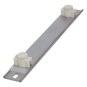
Igloo Ceramic Covers with Mounting Tabs
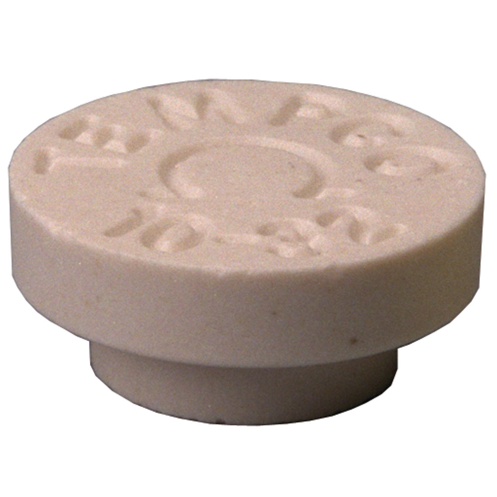
Igloo Ceramic terminal covers consist of two individual ceramic parts. With a tight-fitting cap and a solid base, an Igloo cover will fully insulate any standard 10-32 terminal lug used for electrical wiring hookups. Igloo covers can be assembled on all Channel Strip heaters with Type T1 and Type T4 screw terminals. Three different types of Igloo bases are available for your wiring convenience. Double Port In-Line, Double Port 90° and Single Port. When ordering, specify the type of Igloo.
Igloo Ceramic terminal covers consist of two individual ceramic parts. With a tight-fitting cap and a solid base, an Igloo cover will fully insulate any standard 10-32 terminal lug used for electrical wiring hookups. Igloo covers can be assembled on all Channel Strip heaters with Type T1 and Type T4 screw terminals. Three different types of Igloo bases are available for your wiring convenience. Double Port In-Line, Double Port 90° and Single Port. When ordering, specify the type of Igloo.
Type C6
Type C7
Type C8
Ceramic Cap
Description
Double Port In-Line
Double Port 90°
Single Port
Part #
CER-101-104
CER-101-106
CER-101-107
CER-102-101
Scroll for more
Type C: Terminal Box (General Purpose) with Mounting Tabs
Terminal box has a 1/2″ trade size knockout (actual diameter 7/8″). Box provides excellent protection to exposed terminals. If armor-protected lead wires are required, specify armor and lead length.
Type C: Terminal Box (General Purpose) with Mounting Tabs
Terminal box has a 1/2″ trade size knockout (actual diameter 7/8″). Box provides excellent protection to exposed terminals. If armor-protected lead wires are required, specify armor and lead length.
Type CA: No cable or braid Type CB: Galvanized cable Type CC: Stainless steel cable Type CD: Wire braid
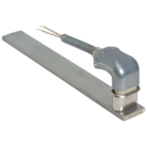
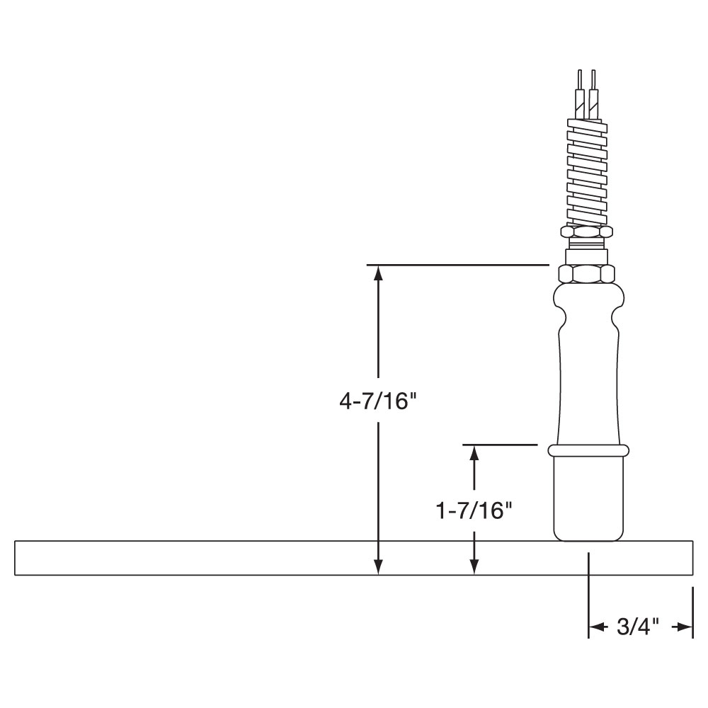
Type P: Quick Disconnect Plugs with Mounting Tabs
High-Temperature Quick Disconnect Plug. If armor protected lead wires are required, specify armor and lead length.
High-Temperature Quick Disconnect Plug. If armor protected lead wires are required, specify armor and lead length.
Maximum Amps: 10 at 240VA
Maximum Volts: 250
Type P1A: Cup only (UT900) Type P1B: Cup and straight plug (H900) Type P1C: Cup and 90° plug (HW900) Type P1D: Cup, straight plug and galvanized cable Type P1G: Cup, 90° plug and galvanized cable
Igloo Ceramic Covers
Igloo Ceramic terminal covers consist of two individual ceramic parts. With a tight-fitting cap and a solid base, an Igloo cover will fully insulate any standard 10-32 terminal lug used for electrical wiring hookups. Igloo covers can be assembled on all Channel Strip heaters with Type T1 and Type T4 screw terminals. Three different types of Igloo bases are available for your wiring convenience. Double Port In-Line, Double Port 90° and Single Port. When ordering, specify the type of Igloo.
Igloo Ceramic terminal covers consist of two individual ceramic parts. With a tight-fitting cap and a solid base, an Igloo cover will fully insulate any standard 10-32 terminal lug used for electrical wiring hookups. Igloo covers can be assembled on all Channel Strip heaters with Type T1 and Type T4 screw terminals. Three different types of Igloo bases are available for your wiring convenience. Double Port In-Line, Double Port 90° and Single Port. When ordering, specify the type of Igloo.
Type C6
Type C7
Type C8
Ceramic Cap
Description
Double Port In-Line
Double Port 90°
Single Port
Part #
CER-101-104
CER-101-106
CER-101-107
CER-102-101
Scroll for more
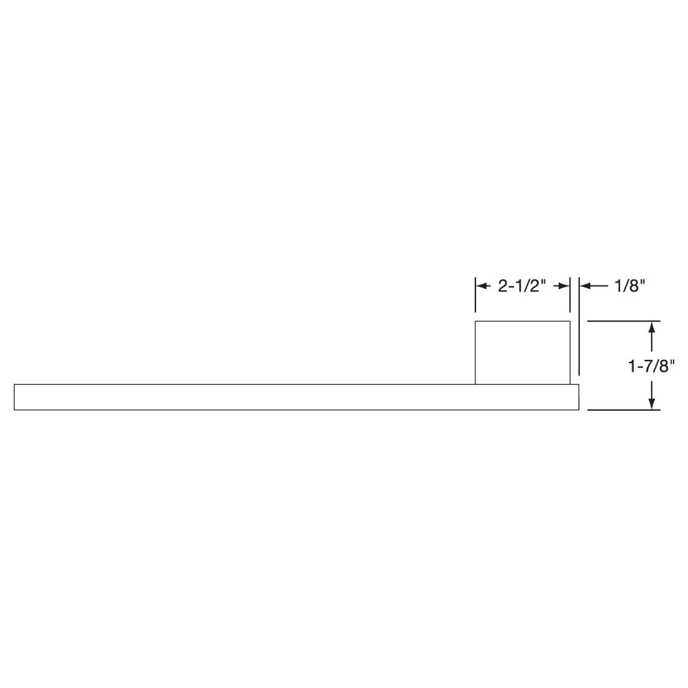
Type C: Terminal Box (General Purpose)
Terminal box has a 1/2″ trade size knockout (actual diameter 7/8″). Box provides excellent protection to exposed terminals. If armor-protected lead wires are required, specify armor and lead length.
Terminal box has a 1/2″ trade size knockout (actual diameter 7/8″). Box provides excellent protection to exposed terminals. If armor-protected lead wires are required, specify armor and lead length.
Type CA: No cable or braid Type CB: Galvanized cable Type CC: Stainless steel cable Type CD: Wire braid
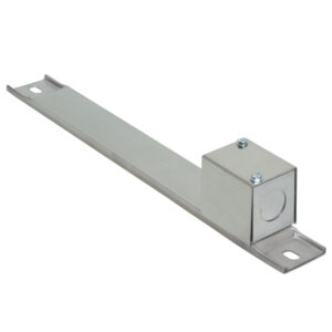
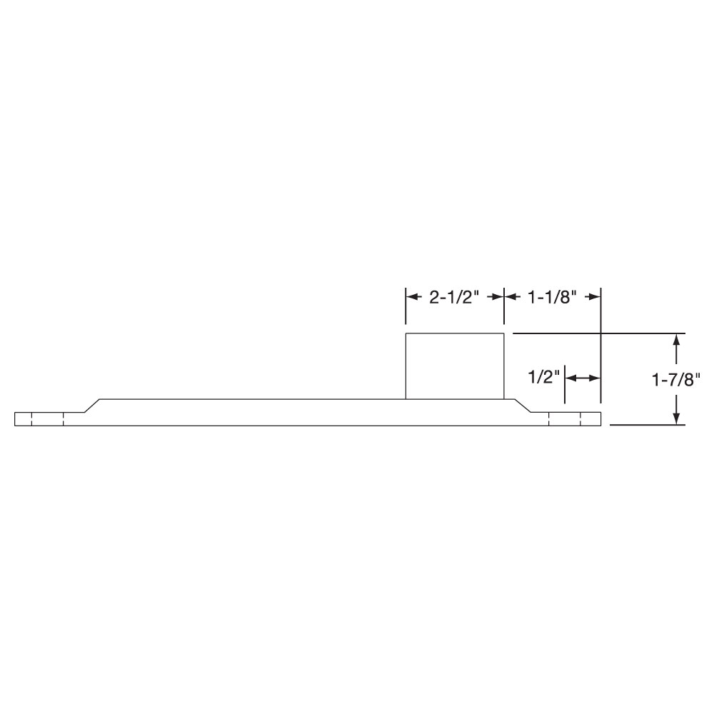
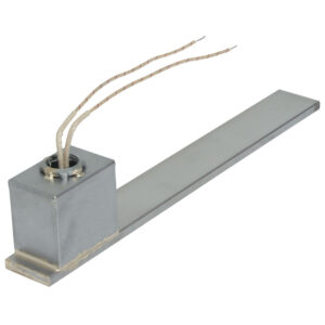
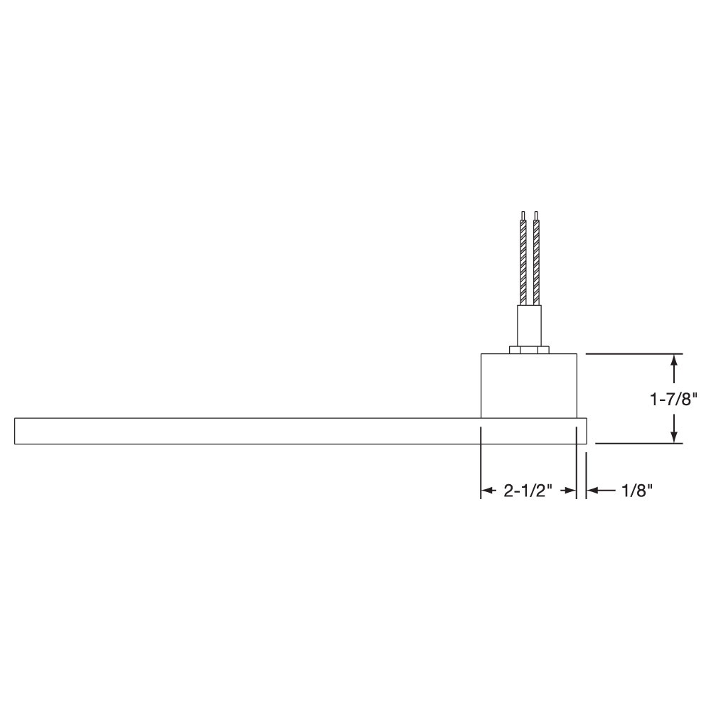
Type MP: Welded Terminal Box
Specially designed box is welded to the Channel Strip Heater and potted with epoxy. The ends of the heater are also welded. Leads exit through a 1/2″ NPT nut that can be located at the top or in the front of the box. Armor cable can be supplied with the male fitting, providing a completely sealed Channel Strip. Available on 11⁄2″ wide heaters only. 10″ long leads standard; if longer leads are required, specify.
Specially designed box is welded to the Channel Strip Heater and potted with epoxy. The ends of the heater are also welded. Leads exit through a 1/2″ NPT nut that can be located at the top or in the front of the box. Armor cable can be supplied with the male fitting, providing a completely sealed Channel Strip. Available on 11⁄2″ wide heaters only. 10″ long leads standard; if longer leads are required, specify.
Maximum Amps: 25
Maximum Volts: 480
Type MPA: Box only Type MPB: Box with prewired galvanized cable Type MPC: Box with prewired stainless steel cable Type MPD: Box with prewired wire braid
Type P: Quick Disconnect Plugs
High-Temperature Quick Disconnect Plug. If armor protected lead wires are required, specify armor and lead length.
High-Temperature Quick Disconnect Plug. If armor protected lead wires are required, specify armor and lead length.
Maximum Amps: 10 at 240VA
Maximum Volts: 250
Type P1A: Cup only (UT900) Type P1B: Cup and straight plug (H900) Type P1C: Cup and 90° plug (HW900) Type P1D: Cup, straight plug and galvanized cable Type P1G: Cup, 90° plug and galvanized cable
📦
Request Other Termination Option
If your filter selections do not return your desired results from our standard configurations, please continue to select your Specifications. When you are finished, save your selections in the Wish List (using the button at the right of this page) and follow the steps to submit them to Tempco.
If your filter selections do not return your desired results from our standard configurations, please continue to select your Specifications. When you are finished, save your selections in the Wish List (using the button at the right of this page) and follow the steps to submit them to Tempco.
Power Variations
No options available for this section based on your selections
Type DW: Distributed Wattage
Channel strip and finned channel strip heaters can be designed to vary the wattage along the length of the heater. Specify number of zones and the required watts and length per zone. Shown with T4 termination.
Channel strip and finned channel strip heaters can be designed to vary the wattage along the length of the heater. Specify number of zones and the required watts and length per zone. Shown with T4 termination.
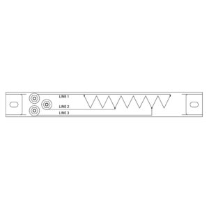
Type 3PH: Three Phase
In order to minimize the gauge of the wiring on high wattage channel strip and finned channel strip heaters, 3-phase elements can be designed.
In order to minimize the gauge of the wiring on high wattage channel strip and finned channel strip heaters, 3-phase elements can be designed.
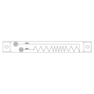
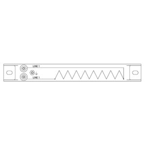
Type DV_: Dual Voltage (1 and 2)
Channel strip and finned channel strip heaters can be designed using 3-wire series/parallel circuits for dual vltage applications. Whether the heater is run on the high or low voltage, the wattage will be the same.
Channel strip and finned channel strip heaters can be designed using 3-wire series/parallel circuits for dual vltage applications. Whether the heater is run on the high or low voltage, the wattage will be the same.
DV1: 120/240 volts
DV2: 240/480 volts
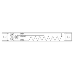
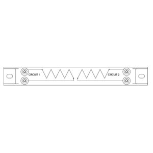
Type DWV: Dual Circuits
Independent resistance elements can be designed in a single channel strip or finned channel strip heater for added versatility.
For those applications requiring a separate ground lead attached to the channel strip or finned channgel strip heater sheath.
Agency Approvals (if required)
No options available for this section based on your selections
📦
CSA Standard
Channel Strip and Finned Channel Strip Heaters have been certified as Recognized Components by Underwriters Laboratories (File Number E65652) under CCN KSOT2/8 to meet UL standard 499. This file specifies the end use limitations and conditions of acceptability for the use of this type of heater. For additional information consult Tempco. Mica Strip heaters are UL recognized and CSA certified in many design variations. Tempco’s UL file number is E65652 and CSA file number is 043099.
Channel Strip and Finned Channel Strip Heaters have been certified as Recognized Components by Underwriters Laboratories (File Number E65652) under CCN KSOT2/8 to meet UL standard 499. This file specifies the end use limitations and conditions of acceptability for the use of this type of heater. For additional information consult Tempco. Mica Strip heaters are UL recognized and CSA certified in many design variations. Tempco’s UL file number is E65652 and CSA file number is 043099.
📦
UL Standard
Channel Strip and Finned Channel Strip Heaters have been certified as Recognized Components by Underwriters Laboratories (File Number E65652) under CCN KSOT2/8 to meet UL standard 499. This file specifies the end use limitations and conditions of acceptability for the use of this type of heater. For additional information consult Tempco. Mica Strip heaters are UL recognized and CSA certified in many design variations. Tempco’s UL file number is E65652 and CSA file number is 043099.
Channel Strip and Finned Channel Strip Heaters have been certified as Recognized Components by Underwriters Laboratories (File Number E65652) under CCN KSOT2/8 to meet UL standard 499. This file specifies the end use limitations and conditions of acceptability for the use of this type of heater. For additional information consult Tempco. Mica Strip heaters are UL recognized and CSA certified in many design variations. Tempco’s UL file number is E65652 and CSA file number is 043099.
📦
NRTL Standard
Nationally Recognized Testing Laboratory Agency Approvals are available upon request.
UL Standard Channel Strip and Finned Channel Strip Heaters have been certified as Recognized Components by Underwriters Laboratories (File Number E65652) under CCN KSOT2/8 to meet UL standard 499. This file specifies the end use limitations and conditions of acceptability for the use of this type of heater. For additional information consult Tempco. Mica Strip heaters are UL recognized and CSA certified in many design variations. Tempco’s UL file number is E65652 and CSA file number is 043099. Agency Approvals (if required) 1-1/2" Wide by 3/8" Thick 1-1/2" Wide by 5/16" Thick 1" Wide by 5/16" Thick Armor Cable Construction Styles Electrical Terminations Grounding Heat Zones Heater Size (if known) Lead Wire Mounting Tabs No Mounting Tabs Power Formations Power Variations Quick Disconnect Plugs Screw Terminals Terminal Boxes Terminal Covers Termination Options UL Wire Braids Type W2: Wire Braid at Heater End Stainless steel braid over each lead wire offers sharp bending not possible with armor cable, as well as abrasion protection. 10″ long leads standard; if longer leads are required, specify. Not available on heaters with tabs. Maximum Amps: 10 at 240VAC Maximum Volts: 480 CSA NRTL Type W1: Wire Braid at Top with Mounting Tabs Wire braid provides strength and protection to the lead wire insulation, offering sharp bending not possible with armor cable. 10″ of wire braid over 12″ long leads is standard; if longer leads or braid are required, specify. Maximum Amps: 10 at 240VAC Maximum Volts: 480 Type W1: Wire Braid at Top Type T4: Screw Terminals at one end with Mounting Tabs 10-32 Screw Terminals offset (Diagonal) at one end Type T4: Screw Terminals at one end Type T3: Screw Terminals at one end with Mounting Tabs 10-32 Screw Terminals (Parallel) at one end Type T2: Screw Terminals at one end with Mounting Tabs 10-32 Screw Terminals (Tandem) at one end Type T2: Screw Terminals at one end Type T3: Screw Terminals at one end Type T1: Screw Terminals at each end with Mounting Tabs 10-32 Screw Terminals at each end Type T1: Screw Terminals at each end Type R2: Right-Angle Armor Cable at Top with Mounting Tabs Right-angle armor cable prevents contamination from getting into the heater. 10″ of armor over 12″ long leads is standard; if longer leads or armor are required, please specify. Maximum Amps: 10 at 240VAC Maximum Volts: 480 Type R2A: Galvanized cable Type R2B: Stainless steel cable Type R2C: Elbow and leads only (no cable) Type R2: Right-Angle Armor Cable at Top Type R1: Armor Cable at Top with Mounting Tabs Armor cable provides strength and prevents contamination from getting into the heater. 10″ of armor over 12″ long leads are standard; if longer leads or armor are required, please specify. Maximum Amps: 10 at 240VA Maximum Volts: 480 Type R1A: Galvanized cable Type R1B: Stainless steel cable Type R1: Armor Cable at Top Type P: Quick Disconnect Plugs with Mounting Tabs High-Temperature Quick Disconnect Plug. If armor protected lead wires are required, specify armor and lead length. Maximum Amps: 10 at 240VA Maximum Volts: 250 Type P1A: Cup only (UT900) Type P1B: Cup and straight plug (H900) Type P1C: Cup and 90° plug (HW900) Type P1D: Cup, straight plug and galvanized cable Type P1G: Cup, 90° plug and galvanized cable Type P: Quick Disconnect Plugs Type MP: Welded Terminal Box Specially designed box is welded to the Channel Strip Heater and potted with epoxy. The ends of the heater are also welded. Leads exit through a 1/2″ NPT nut that can be located at the top or in the front of the box. Armor cable can be supplied with the male fitting, providing a completely sealed Channel Strip. Available on 11⁄2″ wide heaters only. 10″ long leads standard; if longer leads are required, specify. Maximum Amps: 25 Maximum Volts: 480 Type MPA: Box only Type MPB: Box with prewired galvanized cable Type MPC: Box with prewired stainless steel cable Type MPD: Box with prewired wire braid Type L1: Flexible Lead Wires at Top with Mounting Tabs Flexible lead wires exit from top of heater. 10″ long leads standard; if longer leads are required, specify. Maximum Amps: 10 at 240VAC Maximum Volts: 480 Type L1: Flexible Lead Wires at Top Type L: Flexible Lead Wires at Heater End Flexible lead wires exit from end of heater. 10″ long leads standard; if longer leads are required, specify. Recommended only for tight quarters or where flexibility of the lead wire is required. Maximum Amps: 10 at 240VAC Maximum Volts: 480 Type GL: Ground Lead/Sheath For those applications requiring a separate ground lead attached to the channel strip or finned channgel strip heater sheath. Type DWV: Dual Circuits Independent resistance elements can be designed in a single channel strip or finned channel strip heater for added versatility. Type DW: Distributed Wattage Channel strip and finned channel strip heaters can be designed to vary the wattage along the length of the heater. Specify number of zones and the required watts and length per zone. Shown with T4 termination. Type DV_: Dual Voltage (1 and 2) Channel strip and finned channel strip heaters can be designed using 3-wire series/parallel circuits for dual vltage applications. Whether the heater is run on the high or low voltage, the wattage will be the same. DV1: 120/240 volts DV2: 240/480 volts Type C: Terminal Box (General Purpose) Terminal box has a 1/2″ trade size knockout (actual diameter 7/8″). Box provides excellent protection to exposed terminals. If armor-protected lead wires are required, specify armor and lead length. Type CA: No cable or braid Type CB: Galvanized cable Type CC: Stainless steel cable Type CD: Wire braid Type C: Terminal Box (General Purpose) with Mounting Tabs Type 3PH: Three Phase In order to minimize the gauge of the wiring on high wattage channel strip and finned channel strip heaters, 3-phase elements can be designed. Request Other Termination Option If your filter selections do not return your desired results from our standard configurations, please continue to select your Specifications. When you are finished, save your selections in the Wish List (using the button at the right of this page) and follow the steps to submit them to Tempco. Request Other Electrical Termination If your filter selections do not return your desired results from our standard configurations, please continue to Refine Results for your specifications. When you are finished, save your selections with the Save Results for Quote button (at the right of this page) and choose Request for Quote for further assistance. NRTL Standard Nationally Recognized Testing Laboratory Agency Approvals are available upon request. Igloo Ceramic Covers with Mounting Tabs Igloo Ceramic terminal covers consist of two individual ceramic parts. With a tight-fitting cap and a solid base, an Igloo cover will fully insulate any standard 10-32 terminal lug used for electrical wiring hookups. Igloo covers can be assembled on all Channel Strip heaters with Type T1 and Type T4 screw terminals. Three different types of Igloo bases are available for your wiring convenience. Double Port In-Line, Double Port 90° and Single Port. When ordering, specify the type of Igloo. Igloo Ceramic Covers CSA Standard Channel Strip Heater With Mounting Tabs Heaters are available with mounting tabs. When supported by mounting tabs, the terminal end should be secured firmly. Opposite end should be loose to allow for thermal expansion. Mounting Slot Size Standard 5/16″ × 1/2″ Special Bushings 1/2″ × 5/8″ Channel Strip Heater Without Mounting Tabs Heaters without mounting tabs have ends that are silver soldered shut to prevent moisture and contaminants from entering the heater. For surface mounting installations, Channel Strip heaters must be securely clamped along their entire length to a smooth metal surface.