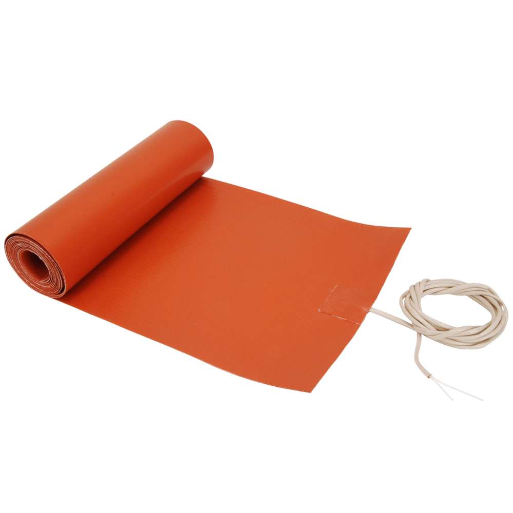
Silicone Rubber Heaters are available as wire wound or etched foil. Wire wound elements consist of the resistance wire wound on a fiberglass cord for support and stability. Etched foil heaters are made with a thin metal foil (.001”) as the resistance element. Wire wound is recommended and preferred for small to medium size quantities, medium to large sized heaters, and to produce prototypes to prove out the design parameters prior to entering into large volume production runs with etched foil.
No options available for this section based on your selections
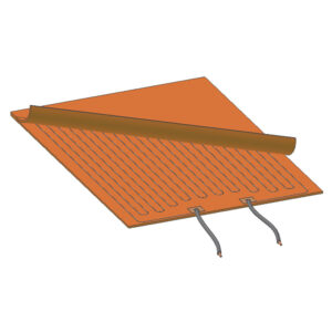
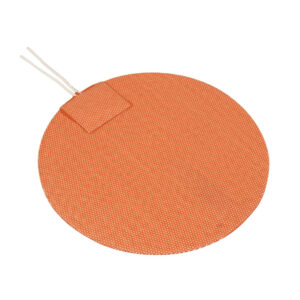
Wire-Wound Element Construction
Silicone Rubber heaters with wire-wound elements provide excellent physical strength capable of withstanding repeated flexing without compromising the life and performance of the heater. They are also very effective for manufacturing geometrically challenged shapes, including three dimensional ones. The wire-wound process is recommended and preferred for small to medium size quantities, medium to large size heaters, and to produce prototypes to prove out the design parameters prior to entering into large volume production runs when using etched foil.
Silicone Rubber heaters with wire-wound elements provide excellent physical strength capable of withstanding repeated flexing without compromising the life and performance of the heater. They are also very effective for manufacturing geometrically challenged shapes, including three dimensional ones. The wire-wound process is recommended and preferred for small to medium size quantities, medium to large size heaters, and to produce prototypes to prove out the design parameters prior to entering into large volume production runs when using etched foil.
The wire-wound element process consists of resistance wire wound on a fiberglass cord for added support and flexibility. The wire-wound element is laid out in a special designed pattern to ensure uniform heat profile and to conform to the size and shape of the silicone rubber heater, avoiding holes and cutouts, or to concentrate the heat profile in a specific section(s) of the heater as the application dictates.
Power lead wires or cord sets are attached to the heater windings with solder and firmly secured in place through a vulcanizing process, ensuring that the assembly becomes homogenous.
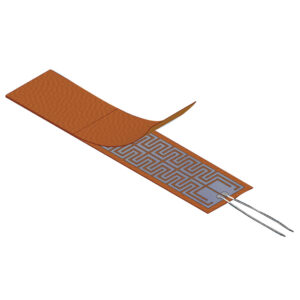
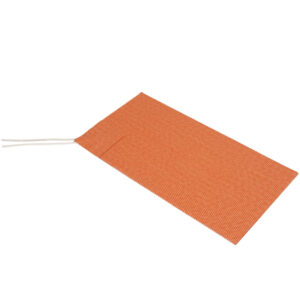
Etched Foil Element Construction
The etched foil heater has exceptional heat transfer compared to wire wound elements, due to its large flat surface area. It can deliver more uniform heat profiles with higher watt densities, providing longer operating heater life. It can also be zoned with distributed wattage or separate heating circuits to compensate for load variations. The etched foil process is recommended for small size heaters in large quantities.
The etched foil heater has exceptional heat transfer compared to wire wound elements, due to its large flat surface area. It can deliver more uniform heat profiles with higher watt densities, providing longer operating heater life. It can also be zoned with distributed wattage or separate heating circuits to compensate for load variations. The etched foil process is recommended for small size heaters in large quantities.
Etched Foil Silicone Rubber heaters are made with a thin metal foil (.001″), usually a nickel base alloy, as the resistance element. The resistance pattern to be etched is designed in CAD and transferred to the foil, which is laminated to the insulating substrate. The element/substrate is then processed through an acid spray to produce the desired resistance pattern.
The top layer is then added and vulcanized for silicone rubber or laminated for Kapton heaters. For silicone rubber heaters, lead wires are then attached to the heater and insulated with
additional silicone rubber to
complete the heater. For Kapton® heaters, lead wires are attached to the heater and insulated with epoxy cement to complete the heater.
Lead Exit Locations
No options available for this section based on your selections
Lead exit specified by customer. Please include drawing when submitting to Tempco.
Electrical Terminations
No options available for this section based on your selections
Teflon® Coated Lead Wire
Tempco’s standard leads are 10″ long, Teflon® insulated, flexible, stranded, plated copper wire. Stripped: 1/4″ UL1180 rated 300V 200°C UL1199 rated 600V 200°C The lead connections are insulated with vulcanized silicone rubber, which also acts as a strain relief.
Tempco’s standard leads are 10″ long, Teflon® insulated, flexible, stranded, plated copper wire. Stripped: 1/4″ UL1180 rated 300V 200°C UL1199 rated 600V 200°C The lead connections are insulated with vulcanized silicone rubber, which also acts as a strain relief.
HPN Cord
For portable heaters, a two-conductor neoprene cordset can be vulcanized to the heater in any desired length.
For portable heaters, a two-conductor neoprene cordset can be vulcanized to the heater in any desired length.
HPN Cord and Plug
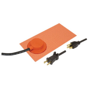
A two-conductor neoprene cord and plug set can be vulcanized to the heater. Standard Length: 6 ft. (1.83 M), 7 ft. (2.13M), or custom length as specified. Supplied with standard straight blade ungrounded plug, or grounded plug. 120Vac only. 2-Pole 2 wire non-grounding (NEMA 1-15P) 2-Pole 3 wire grounding (NEMA 5-15P)
A two-conductor neoprene cord and plug set can be vulcanized to the heater. Standard Length: 6 ft. (1.83 M), 7 ft. (2.13M), or custom length as specified. Supplied with standard straight blade ungrounded plug, or grounded plug. 120Vac only. 2-Pole 2 wire non-grounding (NEMA 1-15P) 2-Pole 3 wire grounding (NEMA 5-15P)
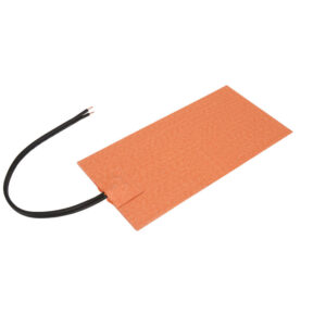
SJO Cord
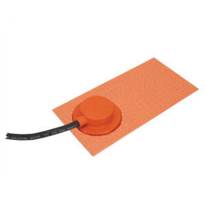
For industrial applications, SJO heavy duty power cords can be attached to the heaters in any desired length.
For industrial applications, SJO heavy duty power cords can be attached to the heaters in any desired length.
SJO Cord and Plug
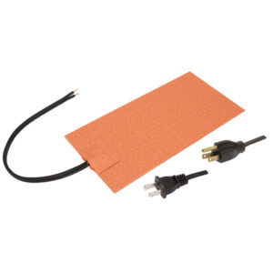
SJO heavy duty power cord and plug set can be attached to the heaters. Standard Length: 6 ft. (1.83 M), or custom length as specified. Supplied with standard straight blade ungrounded plug, or grounded plug. 120Vac only. (For 240Vac see page 15-15 for optional plugs) 2-Pole 2 wire non-grounding (NEMA 1-15P) 2-Pole 3 wire grounding (NEMA 5-1
SJO heavy duty power cord and plug set can be attached to the heaters. Standard Length: 6 ft. (1.83 M), or custom length as specified. Supplied with standard straight blade ungrounded plug, or grounded plug. 120Vac only. (For 240Vac see page 15-15 for optional plugs) 2-Pole 2 wire non-grounding (NEMA 1-15P) 2-Pole 3 wire grounding (NEMA 5-1
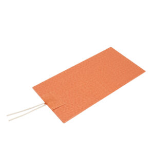
Silicone Rubber Leads
Ensures a moisture seal on the heater. Due to the similarity in material, the heater will fuse to the leads during the vulcanization process. Silicone rubber leads are more flexible, but are not as abrasion resistant as Teflon® leads.
Ensures a moisture seal on the heater. Due to the similarity in material, the heater will fuse to the leads during the vulcanization process. Silicone rubber leads are more flexible, but are not as abrasion resistant as Teflon® leads.
Termination Options
No options available for this section based on your selections
📦
Crimp connectors
Crimp Connectors: insulated or non-insulated Ring Terminal Spade Terminal 1/4″ Female Straight Disconnect 1/4″ Female Right-Angle Disconnect Miniature Connectors: example – Molex
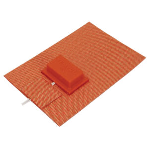
Used to encase lead exit and optional snap action thermostat. Shown with SJO cord rated -50°C to 105°C.
📦
Sleeving
Various materials can be put over Teflon® or Silicone Rubber leads to provide mechanical or abrasion protection. The leads exit the heater as a single unit. Silicone Rubber/Fiberglass Sleeving (356°F/180°C) Heat Shrink Sleeving
Various materials can be put over Teflon® or Silicone Rubber leads to provide mechanical or abrasion protection. The leads exit the heater as a single unit. Silicone Rubber/Fiberglass Sleeving (356°F/180°C) Heat Shrink Sleeving
Mounting Methods
No options available for this section based on your selections
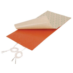
PSA (and PSA Plus)
For ease of attachment, specify PSA. Installation is simple: just peel off the protective liner and apply. It will adhere to most clean smooth surfaces. Care must be taken when installing to attain a smooth, consistent, uniform bond to achieve maximum results.
Maximum Temperature:
Continuous – 300°F (149°C)
Intermittent – 500°F (260°C)
Recommended Watt Density: Under 5 W/in2 (0.78 W/cm2)
PSA Plus A layer of aluminum foil is vulcanized to the back of the heater for added heat dissipation prior to the application of PSA.
To obtain the expected life of Silicone Rubber, care must be taken to mount correctly. Regardless of the mounting technique used, do not trap any air under the heater; this can cause hot spots and possible premature heater failure. Use a rubber roller over the heater surface to assure good adhesion.
Factory Vulcanizing
Flexible heaters can be factory vulcanized to bare or anodized aluminum, Stainless Steel, Marble, or other hard surfaces for permanent attachment and excellent heat transfer. The uncured silicone rubber heater is placed on the metal part and placed in the vacuum oven where the heater vulcanizes and adheres to the part in one operation. This procedure forms an extremely strong permanent bond with most metals due to the fact that the silicone rubber flows into and fills the micro structure in the surface of the metal. The metal part can be manufactured by Tempco or supplied by the customer. Consult Tempco for other materials including granite.
Flexible heaters can be factory vulcanized to bare or anodized aluminum, Stainless Steel, Marble, or other hard surfaces for permanent attachment and excellent heat transfer. The uncured silicone rubber heater is placed on the metal part and placed in the vacuum oven where the heater vulcanizes and adheres to the part in one operation. This procedure forms an extremely strong permanent bond with most metals due to the fact that the silicone rubber flows into and fills the micro structure in the surface of the metal. The metal part can be manufactured by Tempco or supplied by the customer. Consult Tempco for other materials including granite.
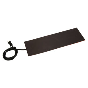
Magnetic Mounting
A flexible magnetic material can be attached to the back of a silicone rubber flexible heater. Will adhere to many varieties of steel. Ideal for those situations were you need to “Slap On” some heat! Specify when requesting a quote.
A flexible magnetic material can be attached to the back of a silicone rubber flexible heater. Will adhere to many varieties of steel. Ideal for those situations were you need to “Slap On” some heat! Specify when requesting a quote.
Maximum Temperature: 200°F / 93°C
Maximum Watt Density: 1 W/in2 (0.16 W/cm2)
Maximum Width: 24″ (610 mm)
Field Applied Adhesive
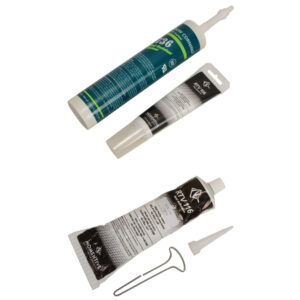
For a field applied permanent bond, a room temperature and ambient humidity curing silicone rubber adhesive is recommended. Tempco offers two types that will retain physical and electrical properties up to 500°F (260°C). When using RTV adhesive, cover the heater completely with a thin layer of RTV, position the heater in place, and use a small roller to remove air bubbles, which could cause hot spots and lead to premature failure of the heater.
For a field applied permanent bond, a room temperature and ambient humidity curing silicone rubber adhesive is recommended. Tempco offers two types that will retain physical and electrical properties up to 500°F (260°C). When using RTV adhesive, cover the heater completely with a thin layer of RTV, position the heater in place, and use a small roller to remove air bubbles, which could cause hot spots and lead to premature failure of the heater.
RTV106 — a red, paste consistency, high-temperature resistant adhesive sealant. Part Number: SEA-102-109, 10.1 ounces Part Number: SEA-102-105, 2.8 ounces
RTV116 — a red, pourable, high-temperature resistant adhesive sealant that will flow or self-level on a surface. Part Number: SEA-102-102, 9.5 ounces
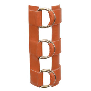
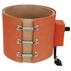
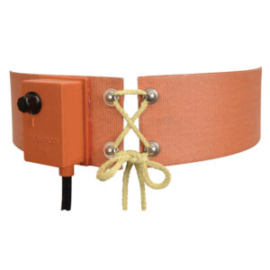
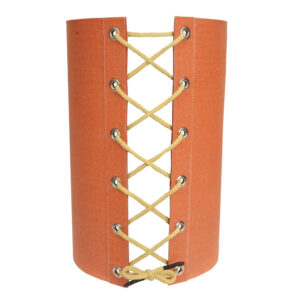
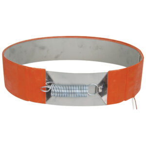
D-Rings and Straps
Mechanical fasteners are available for applications where flexible heaters must be detachable from cylindrical parts.
Mechanical fasteners are available for applications where flexible heaters must be detachable from cylindrical parts.
Clamping
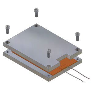
Flexible heaters may be applied by clamping or compression between two rigid materials. The plate surfaces must be ground reasonably smooth. Care must be taken not to damage the heater or pierce the insulation. Mill out an area or cutout in the top plate for the added thickness of the lead exit area. Recommended Maximum Pressure: 40 PSI
Flexible heaters may be applied by clamping or compression between two rigid materials. The plate surfaces must be ground reasonably smooth. Care must be taken not to damage the heater or pierce the insulation. Mill out an area or cutout in the top plate for the added thickness of the lead exit area. Recommended Maximum Pressure: 40 PSI
For added durability, mill out the space for the heater to mount in the same thickness as the heater.
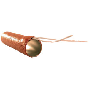
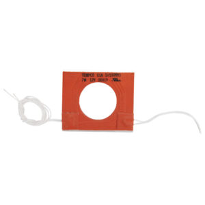
Outside Diameter Mounting
Mechanical fasteners are available for applicationsTempco has developed the techniques necessary to permanently mount silicone rubber heaters to the outside diameters of pipes and medium size vessels. This technique is particularly useful for heated drums and air or gas heating.
Minimum Diameter: 0.5″ (12.7 mm)
Maximum Diameter: 6″ (152.4 mm)
Maximum Length: 20″ (508.0 mm) where flexible heaters must be detachable from cylindrical parts.
3-D Configurations
Dimensional silicone rubber heaters can be vulcanized to fit a shaped outline. This technique is particularly useful for wrapping Silicone Rubber heaters around pipes or small vessels. Custom tooling or special forms may be required.
Dimensional silicone rubber heaters can be vulcanized to fit a shaped outline. This technique is particularly useful for wrapping Silicone Rubber heaters around pipes or small vessels. Custom tooling or special forms may be required.
Sensor Options
No options available for this section based on your selections
Thermocouple
Tempco can incorporate common Type J or K thermocouples almost anywhere on the heater surface. Other thermocouple types can also be used. Standard thermocouple temperature ranges apply. Specify when ordering. See Temperature Sensors for optional plugs.
Tempco can incorporate common Type J or K thermocouples almost anywhere on the heater surface. Other thermocouple types can also be used. Standard thermocouple temperature ranges apply. Specify when ordering. See Temperature Sensors for optional plugs.
Standard length is 10″. Specify sensor lead wire length and the distance from where the sensor leads exit the heater to the heater edge (Dimension X) when ordering.
RTD's
The RTDs (2- or 3-wire) used are platinum thin film 100 ohm @ 100°C. The standard curve is 0.00385 TCR / DIN432760. Other common RTDs such as 1000 ohm can also be used. Specify when ordering. The RTD’s resistance increases with a rise in temperature and is considered the most accurate and stable sensor.
The RTDs (2- or 3-wire) used are platinum thin film 100 ohm @ 100°C. The standard curve is 0.00385 TCR / DIN432760. Other common RTDs such as 1000 ohm can also be used. Specify when ordering. The RTD’s resistance increases with a rise in temperature and is considered the most accurate and stable sensor.
Thermistors
Thermistors are also a resistive-based temperature sensor. They do not generally respond in a linear style and are used in a limited temperature range or at a specific single temperature. Small bead style thermistors can be mounted directly on the heater. The thermistor’s response is generally designed directly into the customer’s electronic control system. Therefore if a thermistor is required, specify manufacturer, specific model number, type and specifications when requesting a quote. Consult Tempco for more information.
Thermistors are also a resistive-based temperature sensor. They do not generally respond in a linear style and are used in a limited temperature range or at a specific single temperature. Small bead style thermistors can be mounted directly on the heater. The thermistor’s response is generally designed directly into the customer’s electronic control system. Therefore if a thermistor is required, specify manufacturer, specific model number, type and specifications when requesting a quote. Consult Tempco for more information.
📦
No Temperature Sensor
A temperature sensor is not needed for this heater.
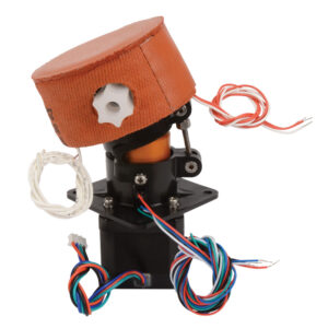
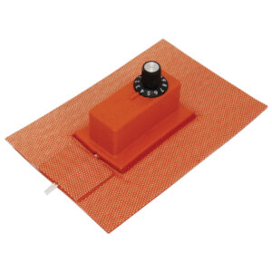
Adjustable thermostats allow the user to dial-in a specific temperature and attain a desired result. The thermostat is enclosed in a molded silicone rubber housing and permanently attached to the heater. The adjustment shaft extends through a pre-formed hole. A high temperature knob is included.
Amps: 12.5A @ 125V, 6.5 A @ 250V
Watts: 1500W @ 120V, 1560W @ 240V
Adjustment Ranges Available: 50 to 425°F (10 to 218°C) 90 to 140°F (32 to 60°C) 100 to 190°F (38 to 88°C) 70 to 190°F (21 to 88°C) 50 to 160°F (10 to 71°C) 70 to 140°F (21 to 60°C)
Minimum Heater Width: 1.75″ (44.5 mm)
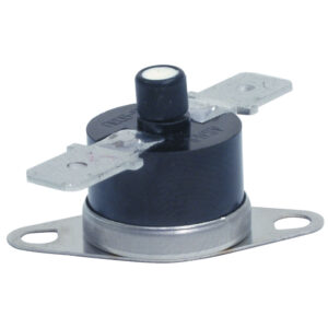
Snap Action High Limit Thermostat
A High Limit with a manual reset push button can also be designed in. Specify when requesting a quote. NOTE: See page 13-83 for stock temperature ratings
A High Limit with a manual reset push button can also be designed in. Specify when requesting a quote. NOTE: See page 13-83 for stock temperature ratings
Creep Action Thermostat
Sustained response, and a slow cutout at the trip point. The creep action thermostat has a slow make/slow break action around setpoint.
Setpoint (opens): available in a limited selection from 50 to 300°F in 10°F increments. Consult Tempco.
Thermal fuses / cutoffs are used as high limit protection devices to guard the object being heated from dangerous temperatures in the event of a primary control device failure. The thermal fuse can be mounted using various methods depending on other options. If the heater does not have a thermostat, the thermal fuse would be mounted under the lead exit patch. If used in conjunction with a thermostat, it could be mounted under the thermostat cover.
Thermal fuses / cutoffs are used as high limit protection devices to guard the object being heated from dangerous temperatures in the event of a primary control device failure. The thermal fuse can be mounted using various methods depending on other options. If the heater does not have a thermostat, the thermal fuse would be mounted under the lead exit patch. If used in conjunction with a thermostat, it could be mounted under the thermostat cover.
Temperature Range: 151 to 464°F (66 to 240°C) Single temperature point only, in
10° to 20° steps. Consult Tempco with your requirements. Voltage: 120/240 Vac Maximum Amperage: 10 Amps, continuous
The thermal cutoff is a one-shot, non-resettable component.
Additional Options
No options available for this section based on your selections
Internal Ground Screen Plane
Some applications may require the heater to be grounded. Due to the fact that the heater sheath is non-conductive, this can only be done artificially. A second layer of insulating material and a conductive grid can be added to the heater. A ground wire is attached to the grid. A less expensive alternative for setting up a ground wire, especially for the required ground lead of a cordset, is to have a “flying ground lead” (6″ long, green) exit the lead patch for attaching to the metal load surface, effectively grounding the process.
Some applications may require the heater to be grounded. Due to the fact that the heater sheath is non-conductive, this can only be done artificially. A second layer of insulating material and a conductive grid can be added to the heater. A ground wire is attached to the grid. A less expensive alternative for setting up a ground wire, especially for the required ground lead of a cordset, is to have a “flying ground lead” (6″ long, green) exit the lead patch for attaching to the metal load surface, effectively grounding the process.
Dual Voltage
Due to the flexibility in circuit design for flexible heaters, heating circuits can be designed to accommodate dual voltage. On dual voltage heaters, three leads, including a common in a different color, are provided for wiring the heater in series for the higher voltage and parallel for the lower voltage. 120/240 Vac or 240/480 Vac can be specified.
Due to the flexibility in circuit design for flexible heaters, heating circuits can be designed to accommodate dual voltage. On dual voltage heaters, three leads, including a common in a different color, are provided for wiring the heater in series for the higher voltage and parallel for the lower voltage. 120/240 Vac or 240/480 Vac can be specified.
Three-Phase Wiring
Heaters can be designed with internal three-phase delta wiring. Three phase WYE wiring is also possible but less preferable in most cases. All 3-phase heaters will have three power leads coming out of the heater. Three phase heaters are typically larger heaters used in high current applications.
Heaters can be designed with internal three-phase delta wiring. Three phase WYE wiring is also possible but less preferable in most cases. All 3-phase heaters will have three power leads coming out of the heater. Three phase heaters are typically larger heaters used in high current applications.
Self-Limiting/Self-Regulating
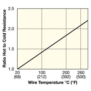
The alloy used for this heater’s resistance wire has a high positive temperature coefficient of resistance that allows the heater to reduce power as temperature increases. This self-regulating feature is ideal for many low temperature applications. This feature can also be beneficial when a fast start-up time is required before the heater power levels off to normal operating temperature. See Chart for Ratio of Hot to Cold Resistance of the Heater wire at various wire temperatures.
The alloy used for this heater’s resistance wire has a high positive temperature coefficient of resistance that allows the heater to reduce power as temperature increases. This self-regulating feature is ideal for many low temperature applications. This feature can also be beneficial when a fast start-up time is required before the heater power levels off to normal operating temperature. See Chart for Ratio of Hot to Cold Resistance of the Heater wire at various wire temperatures.
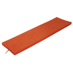
To increase heater efficiency, silicone sponge rubber insulation can be bonded to the top side of the heater. Available thicknesses are 1/16″, 1/8″, 1/4″, 3/8″ or 1/2″. Thermal Conductive Sponge can be use to transfer heat evenly to various surfaces. Available in 1/8″ thickness.
To increase heater efficiency, silicone sponge rubber insulation can be bonded to the top side of the heater. Available thicknesses are 1/16″, 1/8″, 1/4″, 3/8″ or 1/2″. Thermal Conductive Sponge can be use to transfer heat evenly to various surfaces. Available in 1/8″ thickness.
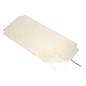
Foil Backing
Aluminum foil can be added to the back of the heater to help dissipate the heat between element runs and eliminate hot spots. Due to the foil, higher watt densities and better temperature uniformity can be attained. The foil would be applied to the back of the heater, on the mounting surface.
Aluminum foil can be added to the back of the heater to help dissipate the heat between element runs and eliminate hot spots. Due to the foil, higher watt densities and better temperature uniformity can be attained. The foil would be applied to the back of the heater, on the mounting surface.
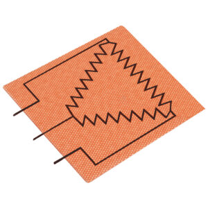
Distrubted Wattage
In order to compensate for heating losses around the edges or mounting holes, the heating circuit can be designed in a distributed wattage pattern. More wattage can be added to the high loss areas to compensate for the higher losses.
In order to compensate for heating losses around the edges or mounting holes, the heating circuit can be designed in a distributed wattage pattern. More wattage can be added to the high loss areas to compensate for the higher losses.
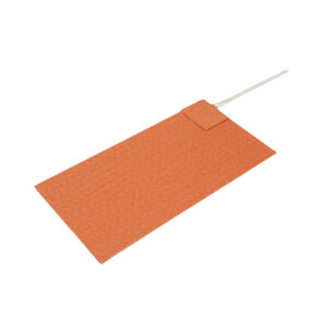
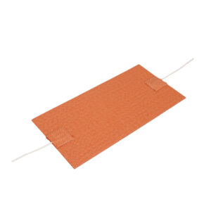
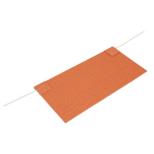
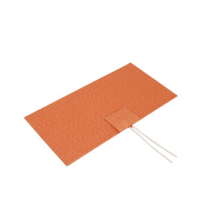
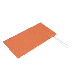
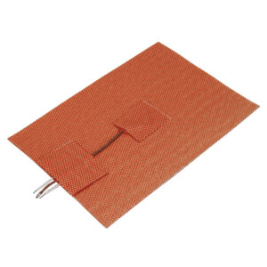
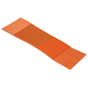
Lead Exit Tab
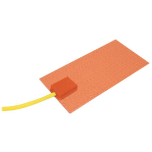
An unheated lead exit tab can be added to the heater for a variety of reasons such as maintaining a rectangular heater with no cold sections or when used in a compression application to remove the lead exit area from between the plates. (Standard 2″ x 2″)
An unheated lead exit tab can be added to the heater for a variety of reasons such as maintaining a rectangular heater with no cold sections or when used in a compression application to remove the lead exit area from between the plates. (Standard 2″ x 2″)
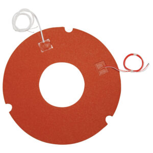
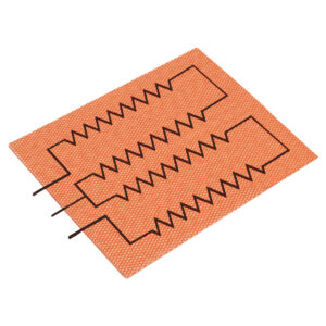
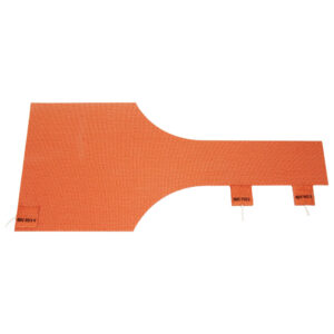
Multiple Zones
Multiple circuit areas can be zoned to compensate for various heating effects desired. In the picture above there are three zones with separate leads (A, B, and C).
Multiple circuit areas can be zoned to compensate for various heating effects desired. In the picture above there are three zones with separate leads (A, B, and C).
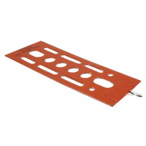
Holes and Cutouts
Holes and cutouts in the surface of a silicone rubber heater can generally be placed anywhere in the heater assembly. Holes and cutouts can be used to allow space for bolts, nuts, temperature sensors, brackets, etc. For most holes and cutouts, a detailed drawing will be required for quoting or ordering.
Holes and cutouts in the surface of a silicone rubber heater can generally be placed anywhere in the heater assembly. Holes and cutouts can be used to allow space for bolts, nuts, temperature sensors, brackets, etc. For most holes and cutouts, a detailed drawing will be required for quoting or ordering.
Wire-Wound Element Construction Silicone Rubber heaters with wire-wound elements provide excellent physical strength capable of withstanding repeated flexing without compromising the life and performance of the heater. They are also very effective for manufacturing geometrically challenged shapes, including three dimensional ones. The wire-wound process is recommended and preferred for small to medium size quantities, medium to large size heaters, and to produce prototypes to prove out the design parameters prior to entering into large volume production runs when using etched foil. The wire-wound element process consists of resistance wire wound on a fiberglass cord for added support and flexibility. The wire-wound element is laid out in a special designed pattern to ensure uniform heat profile and to conform to the size and shape of the silicone rubber heater, avoiding holes and cutouts, or to concentrate the heat profile in a specific section(s) of the heater as the application dictates. Power lead wires or cord sets are attached to the heater windings with solder and firmly secured in place through a vulcanizing process, ensuring that the assembly becomes homogenous. Element Construction Abrasion Protection Additional Options Adjustable Apart Built-In Clamping Construction Options Cord Cord and Plug Electrical Terminations Lead End Options Lead Exit Locations Lead Exit Options Lead Wire Mechanical Fasteners Mounting Methods None Other Permanent Pre-Set Sensor Options Temperature Control Options Termination Options Together Wire-Wound Wiring Options Velcro Straps Mechanical fasteners are available for applications where flexible heaters must be detachable from cylindrical parts. Etched Foil Three-Phase Wiring Heaters can be designed with internal three-phase delta wiring. Three phase WYE wiring is also possible but less preferable in most cases. All 3-phase heaters will have three power leads coming out of the heater. Three phase heaters are typically larger heaters used in high current applications. Thermocouple Tempco can incorporate common Type J or K thermocouples almost anywhere on the heater surface. Other thermocouple types can also be used. Standard thermocouple temperature ranges apply. Specify when ordering. See Temperature Sensors for optional plugs. Standard length is 10". Specify sensor lead wire length and the distance from where the sensor leads exit the heater to the heater edge (Dimension X) when ordering. Thermistors Thermistors are also a resistive-based temperature sensor. They do not generally respond in a linear style and are used in a limited temperature range or at a specific single temperature. Small bead style thermistors can be mounted directly on the heater. The thermistor’s response is generally designed directly into the customer’s electronic control system. Therefore if a thermistor is required, specify manufacturer, specific model number, type and specifications when requesting a quote. Consult Tempco for more information. Thermal Sponge Insulation / Thermal Conductive Sponge To increase heater efficiency, silicone sponge rubber insulation can be bonded to the top side of the heater. Available thicknesses are 1/16″, 1/8″, 1/4″, 3/8″ or 1/2″. Thermal Conductive Sponge can be use to transfer heat evenly to various surfaces. Available in 1/8″ thickness. Thermal Fusing Thermal fuses / cutoffs are used as high limit protection devices to guard the object being heated from dangerous temperatures in the event of a primary control device failure. The thermal fuse can be mounted using various methods depending on other options. If the heater does not have a thermostat, the thermal fuse would be mounted under the lead exit patch. If used in conjunction with a thermostat, it could be mounted under the thermostat cover. Temperature Range: 151 to 464°F (66 to 240°C) Single temperature point only, in 10° to 20° steps. Consult Tempco with your requirements. Voltage: 120/240 Vac Maximum Amperage: 10 Amps, continuous The thermal cutoff is a one-shot, non-resettable component. Teflon® Coated Lead Wire Tempco’s standard leads are 10″ long, Teflon® insulated, flexible, stranded, plated copper wire. Stripped: 1/4″ UL1180 rated 300V 200°C UL1199 rated 600V 200°C The lead connections are insulated with vulcanized silicone rubber, which also acts as a strain relief. SJO Cord For industrial applications, SJO heavy duty power cords can be attached to the heaters in any desired length. SJO Cord and Plug SJO heavy duty power cord and plug set can be attached to the heaters. Standard Length: 6 ft. (1.83 M), or custom length as specified. Supplied with standard straight blade ungrounded plug, or grounded plug. 120Vac only. (For 240Vac see page 15-15 for optional plugs) 2-Pole 2 wire non-grounding (NEMA 1-15P) 2-Pole 3 wire grounding (NEMA 5-1 Sleeving Various materials can be put over Teflon® or Silicone Rubber leads to provide mechanical or abrasion protection. The leads exit the heater as a single unit. Silicone Rubber/Fiberglass Sleeving (356°F/180°C) Heat Shrink Sleeving Snap Action Thermostat – Automatic Reset Quick cutout on rise to temperature. The contacts will open on rise when the temperature increases to the snap point of the calibrated bimetal disc. Setpoint (opens): available from 50 to 450°F in 10°F increments (most thermostats close 20 to 30°F below setpoint) Electrical Ratings: 125 Vac, 15 Amp, 1875W, 250 Vac, 10 Amp, 2500W Minimum Heater Width: 1.312″ Snaps Snap Action High Limit Thermostat A High Limit with a manual reset push button can also be designed in. Specify when requesting a quote. NOTE: See page 13-83 for stock temperature ratings Silicone Rubber Leads Ensures a moisture seal on the heater. Due to the similarity in material, the heater will fuse to the leads during the vulcanization process. Silicone rubber leads are more flexible, but are not as abrasion resistant as Teflon® leads. Self-Limiting/Self-Regulating The alloy used for this heater’s resistance wire has a high positive temperature coefficient of resistance that allows the heater to reduce power as temperature increases. This self-regulating feature is ideal for many low temperature applications. This feature can also be beneficial when a fast start-up time is required before the heater power levels off to normal operating temperature. See Chart for Ratio of Hot to Cold Resistance of the Heater wire at various wire temperatures. RTD's The RTDs (2- or 3-wire) used are platinum thin film 100 ohm @ 100°C. The standard curve is 0.00385 TCR / DIN432760. Other common RTDs such as 1000 ohm can also be used. Specify when ordering. The RTD’s resistance increases with a rise in temperature and is considered the most accurate and stable sensor. PSA (and PSA Plus) For ease of attachment, specify PSA. Installation is simple: just peel off the protective liner and apply. It will adhere to most clean smooth surfaces. Care must be taken when installing to attain a smooth, consistent, uniform bond to achieve maximum results. Maximum Temperature: Continuous – 300°F (149°C) Intermittent – 500°F (260°C) Recommended Watt Density: Under 5 W/in2 (0.78 W/cm2) PSA Plus A layer of aluminum foil is vulcanized to the back of the heater for added heat dissipation prior to the application of PSA. To obtain the expected life of Silicone Rubber, care must be taken to mount correctly. Regardless of the mounting technique used, do not trap any air under the heater; this can cause hot spots and possible premature heater failure. Use a rubber roller over the heater surface to assure good adhesion. Outside Diameter Mounting Mechanical fasteners are available for applicationsTempco has developed the techniques necessary to permanently mount silicone rubber heaters to the outside diameters of pipes and medium size vessels. This technique is particularly useful for heated drums and air or gas heating. Minimum Diameter: 0.5″ (12.7 mm) Maximum Diameter: 6″ (152.4 mm) Maximum Length: 20″ (508.0 mm) where flexible heaters must be detachable from cylindrical parts. Plugs Standard 120 or 240 Vac – straight blade Twist locking plugs, 120 to 480 Vac Specify NEMA or manufacturer’s part number No Temperature Sensor A temperature sensor is not needed for this heater. Multiple Zones Multiple circuit areas can be zoned to compensate for various heating effects desired. In the picture above there are three zones with separate leads (A, B, and C). Magnetic Mounting A flexible magnetic material can be attached to the back of a silicone rubber flexible heater. Will adhere to many varieties of steel. Ideal for those situations were you need to “Slap On” some heat! Specify when requesting a quote. Maximum Temperature: 200°F / 93°C Maximum Watt Density: 1 W/in2 (0.16 W/cm2) Maximum Width: 24″ (610 mm) Lead Exit Tab An unheated lead exit tab can be added to the heater for a variety of reasons such as maintaining a rectangular heater with no cold sections or when used in a compression application to remove the lead exit area from between the plates. (Standard 2″ x 2″) Lead Exit M Exit together at a corner Lead Exit L Exit together the edge of a round heater Lead Exit H Exit together, to one side of the heater length Lead Exit K Exit together from the center of the heater surface Lead Exit J Exit opposite ends, on the same side of the heater length Lead Exit G Lead Exit F Exit together, centered on heater length Lead Exit E Exit opposite ends, to one side of the heater width Lead Exit D Exit opposite ends, centered on heater width Lead Exit C Exit together, to one side of the heater width Lead Exit B Lead Exit A Exit together, centered on heater width Internal Ground Screen Plane Some applications may require the heater to be grounded. Due to the fact that the heater sheath is non-conductive, this can only be done artificially. A second layer of insulating material and a conductive grid can be added to the heater. A ground wire is attached to the grid. A less expensive alternative for setting up a ground wire, especially for the required ground lead of a cordset, is to have a “flying ground lead” (6″ long, green) exit the lead patch for attaching to the metal load surface, effectively grounding the process. HPN Cord and Plug A two-conductor neoprene cord and plug set can be vulcanized to the heater. Standard Length: 6 ft. (1.83 M), 7 ft. (2.13M), or custom length as specified. Supplied with standard straight blade ungrounded plug, or grounded plug. 120Vac only. 2-Pole 2 wire non-grounding (NEMA 1-15P) 2-Pole 3 wire grounding (NEMA 5-15P) HPN Cord For portable heaters, a two-conductor neoprene cordset can be vulcanized to the heater in any desired length. Holes and Cutouts Holes and cutouts in the surface of a silicone rubber heater can generally be placed anywhere in the heater assembly. Holes and cutouts can be used to allow space for bolts, nuts, temperature sensors, brackets, etc. For most holes and cutouts, a detailed drawing will be required for quoting or ordering. Heavy Duty Spring Clamps Grommets and Lacing Cord Foil Backing Aluminum foil can be added to the back of the heater to help dissipate the heat between element runs and eliminate hot spots. Due to the foil, higher watt densities and better temperature uniformity can be attained. The foil would be applied to the back of the heater, on the mounting surface. Factory Vulcanizing Flexible heaters can be factory vulcanized to bare or anodized aluminum, Stainless Steel, Marble, or other hard surfaces for permanent attachment and excellent heat transfer. The uncured silicone rubber heater is placed on the metal part and placed in the vacuum oven where the heater vulcanizes and adheres to the part in one operation. This procedure forms an extremely strong permanent bond with most metals due to the fact that the silicone rubber flows into and fills the micro structure in the surface of the metal. The metal part can be manufactured by Tempco or supplied by the customer. Consult Tempco for other materials including granite. Field Applied Adhesive For a field applied permanent bond, a room temperature and ambient humidity curing silicone rubber adhesive is recommended. Tempco offers two types that will retain physical and electrical properties up to 500°F (260°C). When using RTV adhesive, cover the heater completely with a thin layer of RTV, position the heater in place, and use a small roller to remove air bubbles, which could cause hot spots and lead to premature failure of the heater. RTV106 — a red, paste consistency, high-temperature resistant adhesive sealant. Part Number: SEA-102-109, 10.1 ounces Part Number: SEA-102-105, 2.8 ounces RTV116 — a red, pourable, high-temperature resistant adhesive sealant that will flow or self-level on a surface. Part Number: SEA-102-102, 9.5 ounces Etched Foil Element Construction The etched foil heater has exceptional heat transfer compared to wire wound elements, due to its large flat surface area. It can deliver more uniform heat profiles with higher watt densities, providing longer operating heater life. It can also be zoned with distributed wattage or separate heating circuits to compensate for load variations. The etched foil process is recommended for small size heaters in large quantities. Etched Foil Silicone Rubber heaters are made with a thin metal foil (.001″), usually a nickel base alloy, as the resistance element. The resistance pattern to be etched is designed in CAD and transferred to the foil, which is laminated to the insulating substrate. The element/substrate is then processed through an acid spray to produce the desired resistance pattern. The top layer is then added and vulcanized for silicone rubber or laminated for Kapton heaters. For silicone rubber heaters, lead wires are then attached to the heater and insulated with additional silicone rubber to complete the heater. For Kapton® heaters, lead wires are attached to the heater and insulated with epoxy cement to complete the heater. Dual Voltage Due to the flexibility in circuit design for flexible heaters, heating circuits can be designed to accommodate dual voltage. On dual voltage heaters, three leads, including a common in a different color, are provided for wiring the heater in series for the higher voltage and parallel for the lower voltage. 120/240 Vac or 240/480 Vac can be specified. Distrubted Wattage In order to compensate for heating losses around the edges or mounting holes, the heating circuit can be designed in a distributed wattage pattern. More wattage can be added to the high loss areas to compensate for the higher losses. D-Rings and Straps Customer Specified Lead exit specified by customer. Please include drawing when submitting to Tempco. Crimp connectors Crimp Connectors: insulated or non-insulated Ring Terminal Spade Terminal 1/4″ Female Straight Disconnect 1/4″ Female Right-Angle Disconnect Miniature Connectors: example – Molex Creep Action Thermostat Sustained response, and a slow cutout at the trip point. The creep action thermostat has a slow make/slow break action around setpoint. Setpoint (opens): available in a limited selection from 50 to 300°F in 10°F increments. Consult Tempco. Electrical Ratings: 120 Vac, 12 Amp, 1440W, 240 Vac, 6 Amp, 1440W Flexible heaters may be applied by clamping or compression between two rigid materials. The plate surfaces must be ground reasonably smooth. Care must be taken not to damage the heater or pierce the insulation. Mill out an area or cutout in the top plate for the added thickness of the lead exit area. Recommended Maximum Pressure: 40 PSI For added durability, mill out the space for the heater to mount in the same thickness as the heater. Built-Up Molded Lead Exit Used to encase lead exit and optional snap action thermostat. Shown with SJO cord rated -50°C to 105°C. Boot Hooks and Springs Boot Hooks and Lacing Cord Adjustable Thermostat Adjustable thermostats allow the user to dial-in a specific temperature and attain a desired result. The thermostat is enclosed in a molded silicone rubber housing and permanently attached to the heater. The adjustment shaft extends through a pre-formed hole. A high temperature knob is included. Amps: 12.5A @ 125V, 6.5 A @ 250V Watts: 1500W @ 120V, 1560W @ 240V Adjustment Ranges Available: 50 to 425°F (10 to 218°C) 90 to 140°F (32 to 60°C) 100 to 190°F (38 to 88°C) 70 to 190°F (21 to 88°C) 50 to 160°F (10 to 71°C) 70 to 140°F (21 to 60°C) Minimum Heater Width: 1.75″ (44.5 mm) 3-D Configurations Dimensional silicone rubber heaters can be vulcanized to fit a shaped outline. This technique is particularly useful for wrapping Silicone Rubber heaters around pipes or small vessels. Custom tooling or special forms may be required.