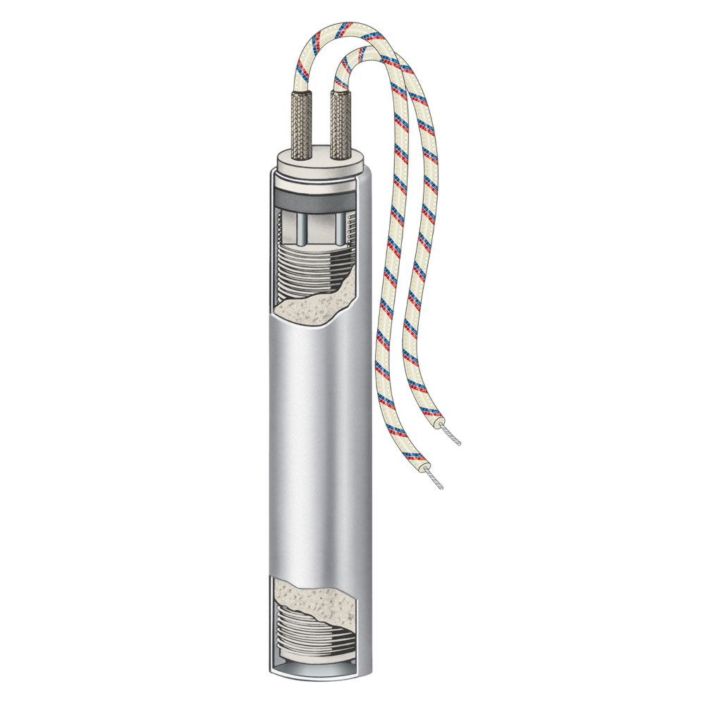
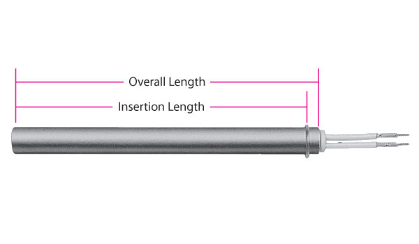
Standard sheath material is 321 Stainless Steel which provides good thermal conductivity, and resistance to corrosion and scaling. Welded end disc made from the same material as the sheath provides a positive seal against moisture and other contaminants. Grade “A” Nickel-Chrome resistance wire precisely wound on a high purity magnesium oxide core places the resistance wire as close to the inside of the sheath as possible. A high purity Magnesium Oxide (MgO) powder is used to fill all remaining space inside the sheath. Heater is then swaged, which compacts the magnesium oxide grains into a solid mass. The standard termination for is Type N, 10″ (254 mm) long nickel conductor lead wires externally connected to solid conductor terminal pins.
No options available for this section based on your selections
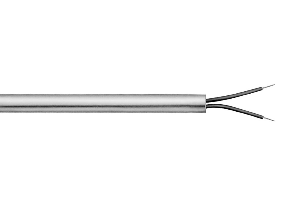
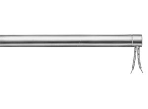
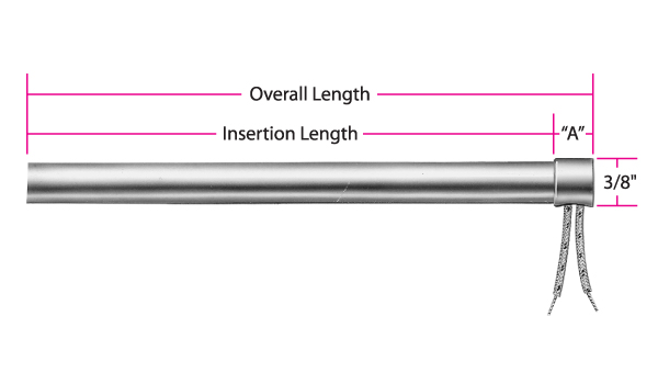
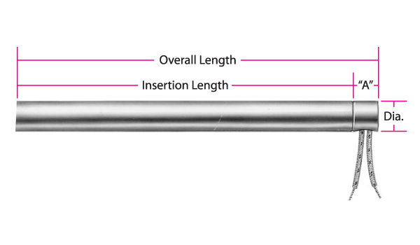
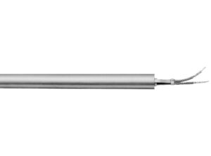
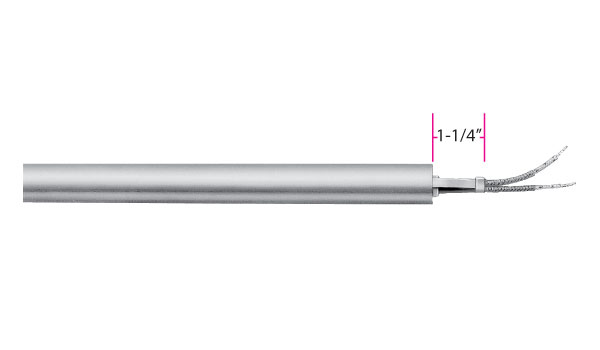
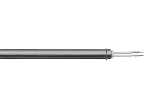
Type N: External Pins with Leads
Standard Termination for Hi-Density and Hi-Density Metric Cartridge Heaters. Flexible stranded lead wires have fiberglass insulation and are connected to 1-1/4″ (32 mm) long solid conductors. Silicone rubber coated fiberglass sleeving insulates the pin/lead wire connection.
Standard Termination for Hi-Density and Hi-Density Metric Cartridge Heaters. Flexible stranded lead wires have fiberglass insulation and are connected to 1-1/4″ (32 mm) long solid conductors. Silicone rubber coated fiberglass sleeving insulates the pin/lead wire connection.
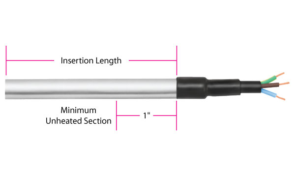
Nominal 3/8″ unheated section at the lead end is required.
Standard lead wire temperature rating: 482°F (250°C)
Silicone rubber coated fiberglass sleeving temperature rating: 392°F (200°C)
Standard 10″ (254 mm) leads. Specify longer leads.
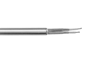
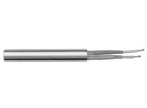
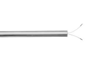
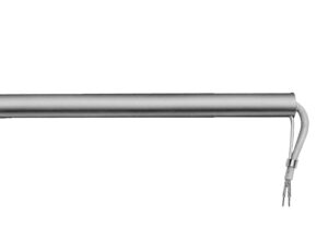
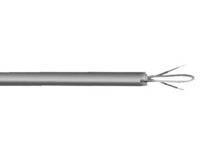
Type F: Internally Connected Flexible Leads
Standard Termination for Low-Density Cartridge Heaters. The fiberglass lead wires are internally connected to the terminal pins. This lead termination provides flexibility, permitting the lead wires to be sharply bent as they exit the heater.
Standard Termination for Low-Density Cartridge Heaters. The fiberglass lead wires are internally connected to the terminal pins. This lead termination provides flexibility, permitting the lead wires to be sharply bent as they exit the heater.
Minimum 3/8″ up to 1″ unheated section at the lead end is required.
Standard lead wire temperature rating for HDC & HDM: 842°F (450°C). Standard lead wire temperature rating for LDC: 482°F (250°C).
Standard 10″ (254 mm) leads. Specify longer leads.
For HDC & HDM heaters, leads longer than 60″ require a splice.
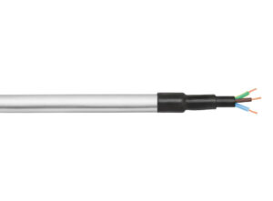
Type M1: Polyolefin Liquid Barrier
A liquid barrier used for low temperature applications primarily in refrigeration or food service applications. The seal bonds to both the heater and the leads.
A liquid barrier used for low temperature applications primarily in refrigeration or food service applications. The seal bonds to both the heater and the leads.
Minimum 1″ unheated section at the lead end is required.
Three conductor SJO type cord.
Available only in certain diameters. Heaters smaller than 1/2″ diameter require an adapter.
Standard 10″ (254 mm) leads. Specify longer leads.
Type M2: Potted End Seal
Potted end seals help to protect the heater from moisture or contamination from plastic material, cleaning solvents, or oils. The bottom end disc seal is welded in.
Potted end seals help to protect the heater from moisture or contamination from plastic material, cleaning solvents, or oils. The bottom end disc seal is welded in.
M2A: Cement potting with silicone varnish. Fiberglass lead wires externally connected. Cement potting temperature rating: 1000°F (538°C) Standard lead wire temperature rating: 482°F (250°C)
M2B: Silicone rubber potting. Silicone rubber lead wires internally connected. Silicone rubber potting temperature rating: 392°F (200°C) Standard lead wire temperature rating: 392°F (200°C)
M2C: High temperature epoxy potting. Teflon® lead wires internally connected. High temp. epoxy potting temp. rating: 450°F (232°C) Standard lead wire temperature rating: 392°F (200°C)
M2D: Low temperature epoxy potting. Teflon® lead wires internally connected. Low temp. epoxy potting temp. rating: 266°F (130°C), UL rated to 194°F (90°C) Standard lead wire temperature rating: 392°F (200°C)
M2E: Cement potting with silicone varnish. Fiberglass lead wires internally connected. Cement potting temperature rating: 1000°F (538°C) Standard lead wire temperature rating: 482°F (250°C)
Minimum of 3/8″ up to 1″ unheated section at the lead end is required.
Standard 10″ (254 mm) leads. Specify longer leads.
NOTE:M2A and M2E are available through the Hi-Density Cartridge Heater Terminator Program for 2nd or 3rd Day Shipping
Type M3: Teflon® End Plug Seal
Standard Termination for Hi-Density Miniature Cartridge Heaters. A moisture resistant Teflon® seal that is swaged in during the manufacturing process with Teflon® insulated lead wire.
Standard Termination for Hi-Density Miniature Cartridge Heaters. A moisture resistant Teflon® seal that is swaged in during the manufacturing process with Teflon® insulated lead wire.
Minimum 3/8″ up to 1″ unheated section at the lead end is required for most heater sizes.
Teflon® seal Temperature rating: 392°F (200°C)
Standard lead wire Temperature rating: 392°F (200°C)
Standard 10″ (254 mm) leads. Specify longer leads. Leads longer than 60″ require a splice.
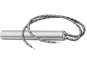
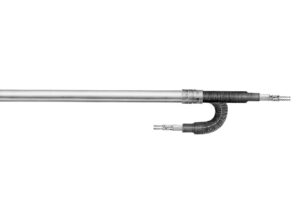
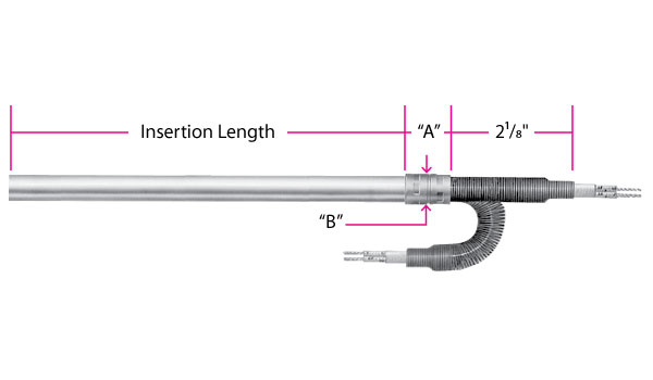
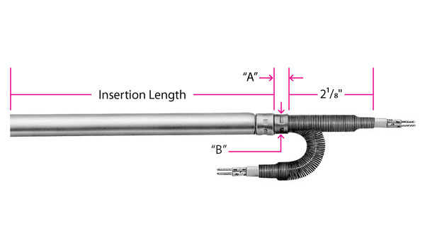
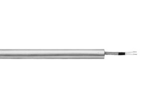
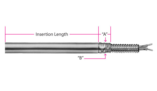
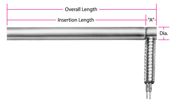
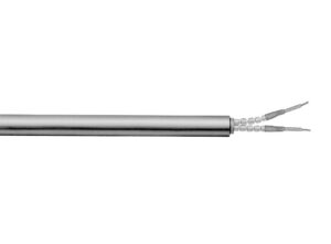
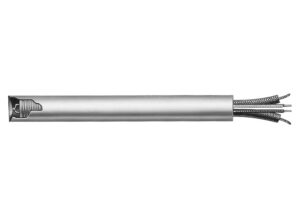
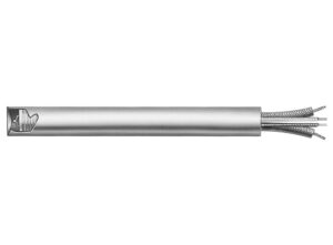
Type SA: Sealed Corrugated Armor Cable
A liquid-proof stainless steel corrugated metal hose is silver brazed to the end of the cartridge heater. The end disc of the heater is also welded or brazed. This termination provides a positive seal against moisture and contamination entering the heater.
A liquid-proof stainless steel corrugated metal hose is silver brazed to the end of the cartridge heater. The end disc of the heater is also welded or brazed. This termination provides a positive seal against moisture and contamination entering the heater.
Minimum 3/8″ up to 1″ unheated section at the lead end is required.
Standard fiberglass lead wire temperature rating for HDC and HDM: 842°F (450°C) Standard fiberglass lead wire temperature rating for LDC: 482°F (250°C)
Standard 10″ (254 mm) cable over 12″ (305 mm) leads. Specify longer leads or cable.
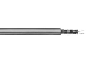
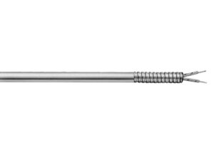
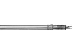
Type S1: Flexible Spring
The leads are reinforced with a steel spring for applications with extreme flexing. The spring is mechanically fastened or silver brazed.
Minimum 3/8″ up to 1″ unheated section at the lead end is required.
Standard fiberglass lead wire temperature rating for HDC and HDM: 842°F (450°C) Standard fiberglass lead wire temperature rating for LDC: 482°F (250°C)
Standard 10″ (254 mm) leads. Specify longer leads.
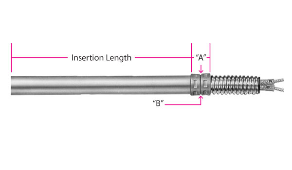
Dimensions for Type S1
Diameter
“A” Dim.
“B” Dim.
in
mm
Fig.
in
mm
in
mm
Hi-Density Cartridge Heaters
1/4
6.35
1
11/16
17.46
5/16
7.94
5/16
7.94
1
11/16
17.46
7/16
11.11
3/8
9.53
1
11/16
17.46
7/16
11.11
1/2
12.70
1
13/16
20.64
9/16
14.29
5/8
15.88
1
1
25.40
3/4
19.05
3/4
19.05
1
1-1/4
31.75
7/8
22.23
1
25.40
2
5/8
15.88
5/8
15.88
Low-Density Cartridge Heaters
3/16
4.76
—
—
—
—
—
1/4
6.35
1
11/16
17.46
5/16
7.94
3/8
9.53
1
11/16
17.46
7/16
11.11
1/2
12.70
1
13/16
20.64
9/16
14.29
5/8
15.88
2
7/16
11.11
9/16
14.29
3/4
19.05
2
1/2
12.70
9/16
14.29
7/8
22.23
2
5/8
15.88
9/16
14.29
15/16
22.81
2
5/8
15.88
5/8
15.88
1
25.40
2
5/8
15.88
5/8
15.88
1-1/4
31.75
2
5/8
15.88
5/8
15.88
Scroll for more
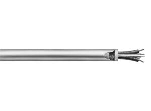
Type W: Wire Braided Leads
Stainless steel braid over fiberglass leads offers sharp bending not possible with armor cable, as well as abrasion protection.
Stainless steel braid over fiberglass leads offers sharp bending not possible with armor cable, as well as abrasion protection.
Minimum 3/8″ up to 1″ unheated section at the lead end is required.
Standard lead wire temperature rating for standard HDC and HDM: 842°F (450°C)
Standard fiberglass lead wire temperature rating for LDC: 482°F (250°C)
Standard 10″ (254 mm) braid over 12″ (305 mm) leads. Specify longer braid/leads
Available through the Hi-Density Cartridge Heater Terminator Program for 2nd or 3rd Day Shipping
*Consult Tempco for Miniature Cartridge Heater dimensions for Type W.
Dimensions for Type W
Diameter
“A” Dim./HD
“A” Dim./LD
in
mm
Fig.
in
mm
in
mm
3/16
4.76
1
*
*
1/4
6.35
1/4
6.35
1
5/16
7.94
5/16
7.94
5/16
7.94
1
3/8
9.53
—
—
3/8
9.53
2
3/8
9.53
3/8
9.53
1/2
12.70
2
7/16
11.11
7/16
11.11
5/8
15.88
2
9/16
14.29
9/16
14.29
3/4
19.05
2
9/16
14.29
9/16
14.29
7/8
22.23
2
—
—
9/16
14.29
15/16
23.81
2
–
–
9/16
14.29
1
25.40
2
9/16
14.29
9/16
14.29
1-1/4
31.75
2
—
—
9/16
14.29
Scroll for more
Type W3: Swaged-In Wire Braided Leads
Stainless steel braid over fiberglass leads offers sharp bending not possible with armor cable, as well as abrasion protection. In addition, Type W3 offers contamination resistance due to the Teflon® seal required for holding the wire braid.
Stainless steel braid over fiberglass leads offers sharp bending not possible with armor cable, as well as abrasion protection. In addition, Type W3 offers contamination resistance due to the Teflon® seal required for holding the wire braid.
Minimum 3/8″ up to 1″ unheated section at the lead end is required.
Teflon® Seal temperature rating: 392°F (200°C)
Standard lead wire temperature rating: 842°F (450°C)
Standard 10″ (254 mm) braid over 12″ (305 mm) leads. Specify longer braid/leads.
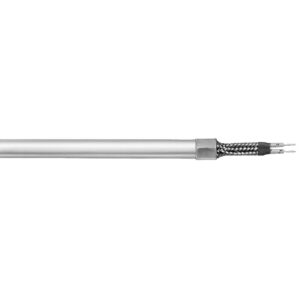
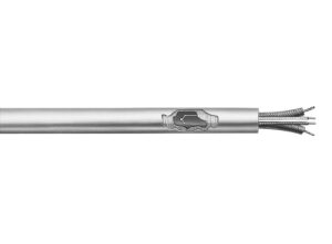
Type CS: Straight Armor Cable Directly Attached to Sheath
The armor cable is directly attached to the cartridge heater, eliminating the coupling, to maintain an overall diameter equal to or smaller than the cartridge diameter.
Type CS: Straight Armor Cable Directly Attached to Sheath
The armor cable is directly attached to the cartridge heater, eliminating the coupling, to maintain an overall diameter equal to or smaller than the cartridge diameter.
Minimum 3/8″ up to 1″ unheated section at the lead end is required.
Heaters with an OD of 3/4″ or larger require reducing diameter washer.
Standard fiberglass lead wire temperature rating for HDC and HDM: 842°F (450°C) Standard fiberglass lead wire temperature rating for LDC: 482°F (250°C)
Standard 10″ (254 mm) cable over 12″ (305 mm) leads. Specify longer leads or cable.
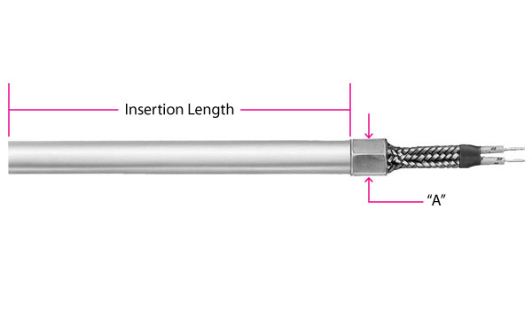
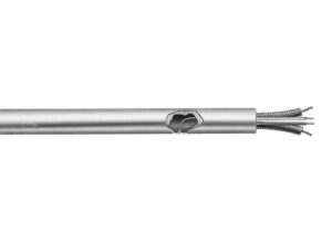
Type C1: Straight Armor Cable with Coupling
Armor cable provides the maximum in protection for abrasive, jagged environments. The coupling between the cartridge and the armor cable is mechanically fastened or silver brazed. *Limited to C1B: SS Cable, Mechanically Fastened for 1/8″ Miniature Cartridge Heaters
Armor cable provides the maximum in protection for abrasive, jagged environments. The coupling between the cartridge and the armor cable is mechanically fastened or silver brazed. *Limited to C1B: SS Cable, Mechanically Fastened for 1/8″ Miniature Cartridge Heaters
C1B: Stainless steel armor cable, mechanically fastened Standard lead wire temperature rating: 482°F (250°C)
C1C: Galvanized armor cable, silver brazed
C1D: Stainless steel armor cable, silver brazed
Standard fiberglass lead wire temperature rating for HDC and HDM: 842°F (450°C) Standard fiberglass lead wire temperature rating for LDC: 482°F (250°C)
Minimum 3/8″ up to 1″ unheated section at the lead end is required.
Standard 10″ (254 mm) cable over 12″ (305 mm) leads. Specify longer leads or cable.
Dimensions for Type C1
Diameter
“A” Dim.
“B” Dim.
Cable
in
mm
Fig.
in
mm
in
mm
Dia.
Hi-Density Cartridge Heaters
1/4
6.35
1
11/16
17.46
5/16
7.94
1/4
5/16
7.94
1
11/16
17.46
7/16
11.11
1/4
3/8
9.53
1
11/16
17.46
7/16
11.11
3/8
1/2
12.70
1
13/16
20.64
9/16
14.29
1/2
5/8
15.88
1
1
25.40
3/4
19.05
1/2
3/4
19.05
1
1-1/4
31.75
7/8
22.23
1/2
1
25.40
2
5/8
15.88
5/8
15.88
1/2
Low-Density Cartridge Heaters
3/16
4.76
—
—
—
—
—
—
1/4
6.35
1
11/16
17.46
5/16
7.94
1/4
3/8
9.53
1
11/16
17.46
7/16
11.11
3/8
1/2
12.70
1
13/16
20.64
9/16
14.29
1/2
5/8
15.88
2
7/16
11.11
9/16
14.29
1/2
3/4
19.05
2
1/2
12.70
9/16
14.29
1/2
7/8
22.23
2
5/8
15.88
9/16
14.29
1/2
15/16
23.81
2
5/8
15.88
5/8
15.88
1/2
1
25.40
2
5/8
15.88
5/8
15.88
1/2
Scroll for more
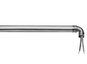
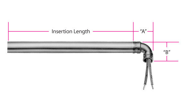
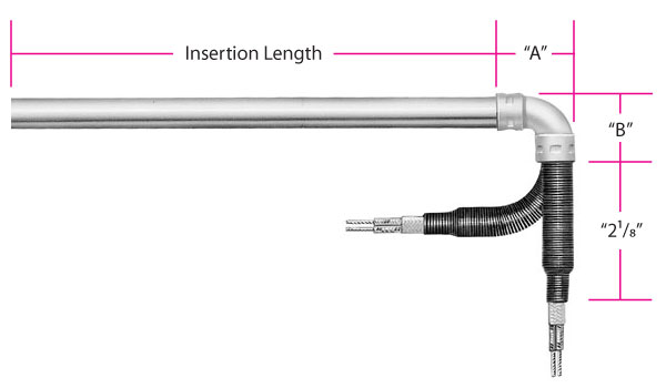
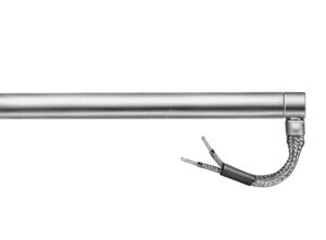
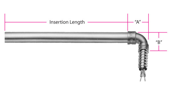
Type R1: Right-Angle Leads with Copper Elbow
This termination is used when space is limited. The copper elbow is mechanically fastened or silver brazed.
This termination is used when space is limited. The copper elbow is mechanically fastened or silver brazed.
R1A: Mechanically fastened
R1B: Silver brazed
Minimum 3/8″ up to 1″ unheated section at the lead end is required.
Standard fiberglass lead wire temperature rating for HDC and HDM: 842°F (450°C) Standard fiberglass lead wire temperature rating for LDC: 482°F (250°C)
Standard 10″ (254 mm) leads. Specify longer leads.
R1A is available through the Hi-Density Cartridge Heater Terminator Program for Same or Next Day Shipping.
Dimensions for Type R1
Diameter
“A” Dim.
“B” Dim.
in
mm
Fig.
in
mm
in
mm
Hi-Density Cartridge Heater
1/4
6.35
1
3/4
19.05
3/4
19.05
5/16
7.94
1
15/16
23.81
15/16
23.81
3/8
9.53
1
15/16
23.81
15/16
23.81
1/2
12.70
1
1-1/4
31.75
1-1/4
31.75
5/8
15.88
1
1-1/4
31.75
1-1/4
31.75
3/4
19.05
1
1-3/4
44.45
1-1/4
31.75
1
25.40
2
1-1/8
28.58
1-3/8
34.93
Low Density Cartridge Heater
3/16
4.76
—
—
—
—
—
1/4
6.35
1
3/4
19.05
3/4
19.05
3/8
9.53
1
15/16
23.81
15/16
23.81
1/2
12.70
1
1-1/4
31.75
1-1/4
31.75
5/8
15.88
2
11/16
17.46
1-1/4
31.75
3/4
19.05
2
3/4
19.05
1-1/4
31.75
7/8
22.23
2
3/4
19.05
1-3/8
34.93
15/16
23.81
2
1-1/8
28.58
1-3/8
34.93
1
25.40
2
1-1/8
28.58
1-3/8
34.93
1-1/4
31.75
2
1-1/8
28.58
1-3/8
34.93
Scroll for more
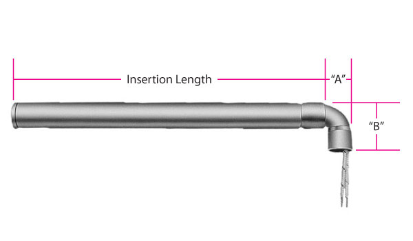
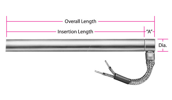
Type R2: Right-Angle Leads
This termination is used when space is limited. Not suitable for abrasive environments. The plain leads are internally connected and they offer flexibility. Various lead end finishes are available as listed below:
This termination is used when space is limited. Not suitable for abrasive environments. The plain leads are internally connected and they offer flexibility. Various lead end finishes are available as listed below:
R2A: Cement potting, no lead end disc Cement potting temperature rating: 1000°F (538°C) Standard fiberglass lead wire temperature rating: 482°F (250°C)
R2B: Cement potting, welded lead end disc Cement potting temperature rating: 1000°F (538°C) Standard fiberglass lead wire temperature rating: 482°F (250°C)
R2C: Silicone rubber potting, welded lead end disc Silicone Rubber potting temperature rating: 392°F (200°C) Standard silicone rubber lead wire temperature rating: 392°F (200°C)
R2D: High temperature epoxy potting, welded lead end disc High Temperature epoxy potting temperature rating: 450°F (232°C) Standard Teflon® lead wire temperature rating: 392°F (200°C)
R2E: Low temperature epoxy potting, welded lead end disc Low Temperature epoxy potting temperature rating: 266°F (130°C) Standard Teflon® lead wire temperature rating: 392°F (200°C)
Minimum 3/8″ up to 1″ unheated section at the lead end is required.
Standard 10″ (254 mm) leads. Specify other lead lengths.
R2A and R2B are available through the Hi-Density Cartridge Heater Terminator Program for 2nd or 3rd Day Shipping
Dimensions for Type R2
Diameter
“A” Dim.
in
mm
Fig.
in
mm
Hi-Density Cartridge Heater
1/4
6.35
1
7/16
11.11
5/16
7.94
1
7/16
11.11
3/8
9.53
2
7/16
11.11
1/2
12.70
2
9/16
14.29
5/8
15.88
2
9/16
14.29
3/4
19.05
2
9/16
14.29
1
25.40
2
5/8
15.88
Low-Density Cartridge Heater
1/4
6.35
1
7/16
11.11
3/8
9.53
2
7/16
11.11
1/2
12.70
2
9/16
14.29
5/8
15.88
2
9/16
14.29
3/4
19.05
2
9/16
14.29
7/8
22.23
2
5/8
15.88
15/16
23.81
2
5/8
15.88
1
25.40
2
5/8
15.88
1-1/4
31.75
2
5/8
15.88
Scroll for more
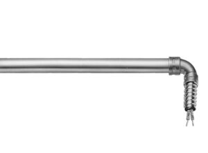
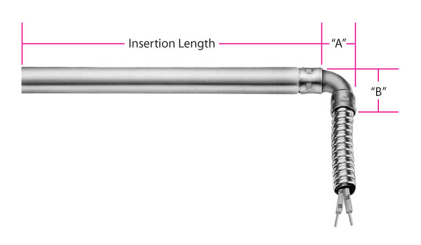
Type S2: Right-Angle Spring
The leads are reinforced with a steel spring for applications with extreme flexing. The spring is mechanically fastened or silver brazed.
The leads are reinforced with a steel spring for applications with extreme flexing. The spring is mechanically fastened or silver brazed.
S2A: Mechanically fastened spring
S2B: Silver brazed spring
Minimum 3/8″ up to 1″ unheated section at the lead end is required.
Standard fiberglass lead wire temperature rating for HDC and HDM: 842°F (450°C) Standard fiberglass lead wire temperature rating for LDC: 482°F (250°C)
Standard 10″ (254 mm) leads. Specify longer leads.
Dimensions for Type S2
Diameter
“A” Dim.
“B” Dim.
in
mm
Fig.
in
mm
in
mm
Hi-Density Cartridge Heaters
1/4
6.35
1
3/4
19.05
3/4
19.05
5/16
7.94
1
15/16
23.81
15/16
23.81
3/8
9.53
1
15/16
23.81
15/16
23.81
1/2
12.70
1
1-1/4
31.75
1-1/4
31.75
5/8
15.88
1
1-1/4
31.75
1-1/4
31.75
3/4
19.05
1
1-3/4
44.45
1-1/4
31.75
1
25.40
2
1-1/8
28.58
1-3/8
34.93
Low-Density Cartridge Heaters
3/16
4.76
—
—
—
—
—
1/4
6.35
1
3/4
19.05
3/4
19.05
3/8
9.53
1
15/16
23.81
15/16
23.81
1/2
12.70
1
1-1/4
31.75
1-1/4
31.75
5/8
15.88
2
11/16
17.46
1-1/4
31.75
3/4
19.05
2
3/4
19.05
1-1/4
31.75
7/8
22.23
2
3/4
19.05
1-3/8
34.93
15/16
23.81
2
1-1/8
28.58
1-3/8
34.93
1
25.40
2
1-1/8
28.58
1-3/8
34.93
1-1/4
31.75
2
1-1/8
28.58
1-3/8
34.93
Scroll for more
Type W1: Right-Angle Wire Braided Leads
Stainless steel braid over fiberglass leads for abrasion protection, mechanically crimped to the cartridge sheath at 90°. Wire braid offers extreme flexibility not possible with armor cable. Various lead end finishes are available as listed below.
Stainless steel braid over fiberglass leads for abrasion protection, mechanically crimped to the cartridge sheath at 90°. Wire braid offers extreme flexibility not possible with armor cable. Various lead end finishes are available as listed below.
W1A: Cement potting and silicone varnish, no lead end disc. Cement potting temperature rating: 1000°F (538°C) Standard lead wire temperature rating: 482°F (250°C)
W1B: Welded lead end disc. Cement potting temperature rating: 1000°F (538°C) Standard lead wire temperature rating: 482°F (250°C)
Minimum 3/8″ up to 1″ unheated section at the lead end is required.
Standard 10″ (254 mm) braid over 12″ (305 mm) leads. Specify longer braid or leads.
Dimensions for Type W1
Diameter
“A” Dim.
in
mm
Fig.
in
mm
Hi-Density Cartridge Heaters
1/4
6.35
1
7/16
11.11
5/16
7.94
1
7/16
11.11
3/8
9.53
2
7/16
11.11
1/2
12.70
2
9/16
14.29
5/8
15.88
2
9/16
14.29
3/4
19.05
2
9/16
14.29
1
25.40
2
5/8
15.88
Low-Density Cartridge Heaters
1/4
6.35
1
7/16
11.11
3/8
9.53
2
7/16
11.11
1/2
12.70
2
9/16
14.29
5/8
15.88
2
9/16
14.29
3/4
19.05
2
9/16
14.29
7/8
22.23
2
5/8
15.88
15/16
23.81
2
5/8
15.88
1
25.40
2
5/8
15.88
1-1/4
31.75
2
5/8
15.88
Scroll for more
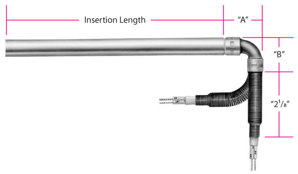
Type C2: Right-Angle Armor Cable with Copper Elbow
Armor cable provides the maximum in protection for abrasive, jagged environments. The copper elbow between the cartridge and the armor cable is mechanically fastened or silver brazed.
Type C2: Right-Angle Armor Cable with Copper Elbow
Armor cable provides the maximum in protection for abrasive, jagged environments. The copper elbow between the cartridge and the armor cable is mechanically fastened or silver brazed.
Minimum 3/8″ up to 1″ unheated section at the lead end is required.
Standard fiberglass lead wire temperature rating for HDC and HDM: 842°F (450°C) Standard fiberglass lead wire temperature rating for LDC:482°F (250°C)
Standard 10″ (254 mm) cable over 12″ (305 mm) leads. Specify longer cable or leads.
C2A and C2B are available through the Hi-Density Cartridge Heater Terminator Program for Same or Next Day Shipping.
Dimensions for Type C2 Hi-Density Cartridge Heaters
Diameter
“A” Dim.
“B” Dim.
Cable
in
mm
Fig.
in
mm
in
mm
Dia.
1/4
6.35
1
3/4
19.05
3/4
19.05
1/4
5/16
7.94
1
15/16
23.81
15/16
23.81
1/4
3/8
9.53
1
15/16
23.81
15/16
23.81
3/8
1/2
12.70
1
1-1/4
31.75
1-1/4
31.75
1/2
5/8
15.88
1
1-1/4
31.75
1-1/4
31.75
1/2
3/4
19.05
1
1-3/4
44.45
1-1/4
31.75
1/2
1
25.40
2
1-1/8
28.58
1-3/8
34.93
1/2
Scroll for more
Dimensions for Type C2 Low Density Cartridge Heaters
Diameter
“A” Dim.
“B” Dim.
Cable
in
mm
Fig.
in
mm
in
mm
Dia.
3/16
4.76
—
—
—
—
—
—
1/4
6.35
1
3/4
19.05
3/4
19.05
1/4
3/8
9.53
1
15/16
23.81
15/16
23.81
3/8
1/2
12.70
1
1-1/4
31.75
1-1/4
31.75
1/2
5/8
15.88
2
11/16
17.46
1-1/4
31.75
1/2
3/4
19.05
2
3/4
19.05
1-1/4
31.75
1/2
7/8
22.23
2
3/4
19.05
1-3/8
34.93
1/2
15/16
23.81
2
1-1/8
28.58
1-3/8
34.93
1/2
1
25.40
2
1-1/8
28.58
1-3/8
34.93
1/2
1-1/4
31.75
2
1-1/8
28.58
1-3/8
34.93
1/2
Scroll for more
Type C3: Right-Angle Armor Cable
Use this termination when space is limited and maximum protection is required. The armor cable is tack welded or silver brazed to the cartridge sheath at 90°. The sheath extension is potted with cement. Various lead end finishes are available as listed below.
Use this termination when space is limited and maximum protection is required. The armor cable is tack welded or silver brazed to the cartridge sheath at 90°. The sheath extension is potted with cement. Various lead end finishes are available as listed below.
C3A: Cement potting and silicone varnish with no lead end disc, galvanized cable
C3B: Cement potting and silicone varnish with no lead end disc, stainless steel cable
C3C: Welded lead end disc, with galvanized cable
C3D: Welded lead end disc, with stainless steel cable
Minimum 3/8″ up to 1″ unheated section at the lead end is required.
Cement potting temperature rating: 1000°F (538°C)
Standard fiberglass lead wire temperature rating: 482°F (250°C)
Standard 10″ (254 mm) armor cable over 12″ (305 mm) leads. Specify longer cable or leads.
Dimensions for Type C3
Diameter
“A” Dim.
Armor Cable
in
mm
Fig.
in
mm
in
mm
Hi-Density Cartridge Heaters
1/4
6.35
1
7/16
11.11
1/4
6.35
5/16
7.94
1
7/16
11.11
1/4
6.35
3/8
9.53
2
7/16
11.11
3/8
9.53
1/2
12.70
2
9/16
14.29
3/8
9.53
5/8
15.88
2
9/16
14.29
1/2
12.70
3/4
19.05
2
9/16
14.29
1/2
12.70
1
25.40
2
5/8
15.88
1/2
12.70
Low-Density Cartridge Heaters
1/4
6.35
1
7/16
11.11
1/4
6.35
3/8
9.53
2
7/16
11.11
3/8
9.53
1/2
12.70
2
9/16
14.29
3/8
9.53
5/8
15.88
2
9/16
14.29
1/2
12.70
3/4
19.05
2
9/16
14.29
1/2
12.70
7/8
22.23
2
5/8
15.88
1/2
12.70
1
25.40
2
5/8
15.88
1/2
12.70
1-1/4
31.75
2
5/8
15.88
1/2
12.70
Scroll for more
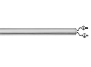
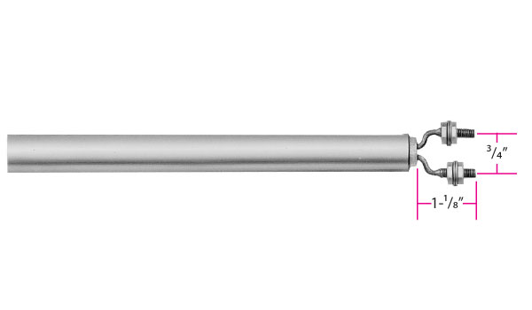
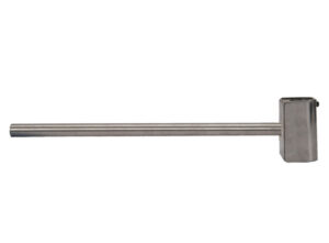
Type T2: Screw Terminals
For use with leads, crimp terminals, or bus bars. Includes washers and nuts.
For use with leads, crimp terminals, or bus bars. Includes washers and nuts.
Minimum 1/2″ unheated section at the lead end is required.
Diameters available: HDC – 5/8″, 3/4″, 1″ HDM – 16 mm and 20 mm
Standard: screw #8-32
Type B: Heat Resistant Ceramic Bead Insulation
The ultimate in high temperature lead protection. Allows for the attachment of flexible leads to the heater away from the high heat area. Used when the ambient temperature exceeds 842°F (450°C).
The ultimate in high temperature lead protection. Allows for the attachment of flexible leads to the heater away from the high heat area. Used when the ambient temperature exceeds 842°F (450°C).
Standard 10″ (254 mm) solid nickel pins insulated with ball and socket construction type ceramic beads.
Available through the Hi-Density Cartridge Heater Terminator Program for Same or Next Day Shipping.
Type BL: Heat Resistant Ceramic Bead Insulation with Leads
High temperature flexible leads are connected away from the high heat area.
Type BL: Heat Resistant Ceramic Bead Insulation with Leads
High temperature flexible leads are connected away from the high heat area.
Standard 6″ (254 mm) solid nickel pins insulated with ball and socket construction type ceramic beads and 10″ (254 mm) fiberglass leads rated at 842°F (450°C). Specify longer leads.
Available through the Hi-Density Cartridge Heater Terminator Program for Same or Next Day Shipping.
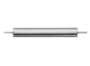
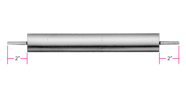
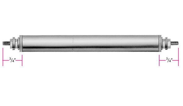
Type T4: Double-End Terminal Pin
For those applications in which wiring from both ends is an advantage. Various seals are available:
Minimum 1″ unheated section at each end is required.
Standard terminal pin length is 2″.
Type F1: Double-End Flexible Leads
For applications in which it is an advantage to wire from both ends. The leads are internally connected and can be bent sharply as they exit the potted ends. Various seals are available:
For applications in which it is an advantage to wire from both ends. The leads are internally connected and can be bent sharply as they exit the potted ends. Various seals are available:
F1A: Fiberglass leads with cement potting seal and silicone varnish Cement potting temperature rating: 1000°F (532°C) Standard lead wire temperature rating: 482°F (250°C)
F1B: Teflon® leads with high temp. moisture resistant epoxy seal High temp. epoxy temperature rating: 450°F (232°C) Standard lead wire temperature rating: 392°F (200°C)
F1C: Teflon® leads with low temp. moisture resistant epoxy seal Low temp. epoxy temperature rating: 266°F (130°C) Standard lead wire temperature rating: 392°F (200°C)
Minimum 1″ unheated section at each end is required.
Standard 10″ leads. Specify longer leads.
Leads longer than 60″ require a splice.
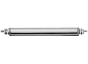
Type T3: Double-End Screw Terminal Leads
A Double-Ended heater with quick change wiring screw terminals. Includes zinc plated washers and nuts.
If your filter selections do not return your desired results from our standard configurations, please continue to Refine Results for your specifications. When you are finished, save your selections with the Save Results for Quote button (at the right of this page) and choose Request for Quote for further assistance.
If your filter selections do not return your desired results from our standard configurations, please continue to Refine Results for your specifications. When you are finished, save your selections with the Save Results for Quote button (at the right of this page) and choose Request for Quote for further assistance.
Termination Options
No options available for this section based on your selections
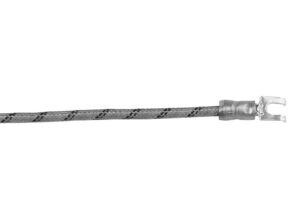
Type S3: Lead Wire Strain Relief
Strain relief clip for leads subject to tension and stress. A “T” type strain relief is silver brazed to the sheath.
Strain relief clip for leads subject to tension and stress. A “T” type strain relief is silver brazed to the sheath and bent at a 90° angle.
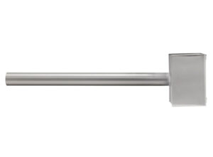
Type E1: General Purpose Terminal Box
General purpose Stainless Steel NEMA 1 electrical enclosure designed to provide protection from electrical shock. The boxes have a 5/8″ conduit knockout and are welded or brazed to the cartridge sheath.
General purpose Stainless Steel NEMA 1 electrical enclosure designed to provide protection from electrical shock. The boxes have a 5/8″ conduit knockout and are welded or brazed to the cartridge sheath.
A termination must be specified separately.
Available through the Hi-Density Cartridge Heater Terminator Program For 2nd or 3rd Day Shipping
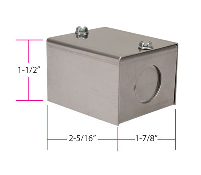
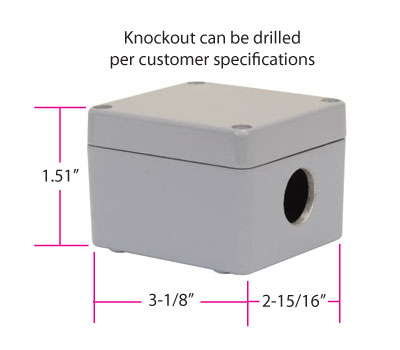
Type E2: Moisture Proof Terminal Box
NEMA 4 aluminum electrical enclosures provide protection from splashing or hose directed water, external condensation and water seepage. The box is mechanically attached to the cartridge sheath.
NEMA 4 aluminum electrical enclosures provide protection from splashing or hose directed water, external condensation and water seepage. The box is mechanically attached to the cartridge sheath.
A single 5/8″ access hole is standard.
A termination must be specified separately.
Type E3: Explosion Resistant Terminal Boxes
General purpose Stainless Steel NEMA 1 electrical enclosure designed to provide protection from electrical shock. The box is welded or brazed to the cartridge sheath.
General purpose Stainless Steel NEMA 1 electrical enclosure designed to provide protection from electrical shock. The box is welded or brazed to the cartridge sheath.
A termination must be specified separately.
Housing E3C Dimensions
Heater
Hub Size
“A”
“B”
“C”
“D”
“E”
Diameter(s)
NPT
(in)
(in)
(in)
(in)
(in)
1/2 & 5/8
1/2-14
2-1/2
2-1/4
2-3/16
5/8
7/8
3/4
3/4-14
2-1/2
2
2
3/4
7/8
1
1-111⁄2
3-1/2
2-5/16
2-3/16
7/8
1
Scroll for more
Housing E3D Dimensions
Heater
Hub Size
“A”
“B”
“C”
“D”
“E”
Diameter(s)
NPT
(in)
(in)
(in)
(in)
(in)
1/2 & 5/8
1/2-14
2-1/2
2-1/4
2-3/16
5/8
7/8
3/4
3/4-14
2-1/2
2-1/2
2-7/16
3/4
7/8
1
1-111⁄2
3-1/2
2-5/16
2-3/16
7/8
1
Scroll for more
Housing E3L Dimensions
Heater
Hub Size
“A”
“B”
“C”
“D”
“E”
Diameter(s)
NPT
(in)
(in)
(in)
(in)
(in)
1/2 & 5/8
1/2-14
2-1/2
2-1/4
2-3/16
5/8
7/8
3/4
3/4-14
2-1/2
2-1/2
2-7/16
3/4
7/8
1
1-111⁄2
3-1/2
2-5/16
2-3/16
7/8
1
Scroll for more
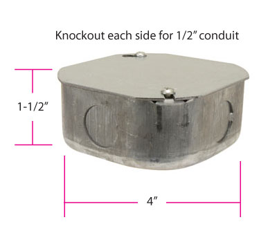
Type E4: General Purpose Terminal Box (mailbox style)
General purpose steel NEMA 1 electrical enclosure designed to provide protection from electrical shock. The box is welded to the cartridge sheath.
Type E4: General Purpose Terminal Box (mailbox style)
General purpose steel NEMA 1 electrical enclosure designed to provide protection from electrical shock. The box is welded to the cartridge sheath.
A termination must be specified separately.
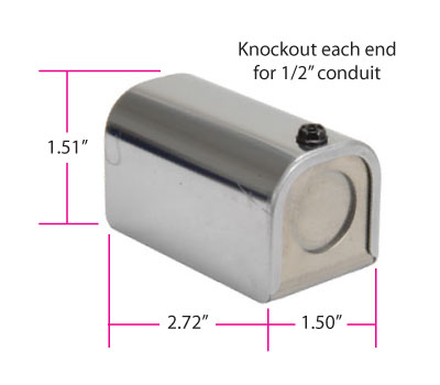
Type E5: Octagon Terminal Box
NEMA 4/7 electrical enclosures provide protection from contaminants, moisture, and hazardous conditions. These housings are screwed onto a heater with a single or double ended Brass or Stainless Steel fitting. A threaded fitting mounting termination must be specified. See pages 2-50 and 2-51. Other terminal box configurations available upon request.
NEMA 4/7 electrical enclosures provide protection from contaminants, moisture, and hazardous conditions. These housings are screwed onto a heater with a single or double ended Brass or Stainless Steel fitting. A threaded fitting mounting termination must be specified. See pages 2-50 and 2-51. Other terminal box configurations available upon request.
Type RT: Ring Terminal
Various types of crimp terminals can be attached to the heater leads to make wiring into applications quick and easy. Non-insulated and insulated with nylon (221°F/105°C) or PVC (194°F/90°C).
Various types of crimp terminals can be attached to the heater leads to make wiring into applications quick and easy. Non-insulated and insulated with nylon (221°F/105°C) or PVC (194°F/90°C).
Type ST: Spade Terminal
Various types of crimp terminals can be attached to the heater leads to make wiring into applications quick and easy. Non-insulated and insulated with nylon (221°F/105°C) or PVC (194°F/90°C).
Various types of crimp terminals can be attached to the heater leads to make wiring into applications quick and easy. Non-insulated and insulated with nylon (221°F/105°C) or PVC (194°F/90°C).
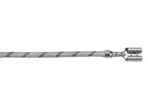
Type QTA: 1/4" Female Straight Quick Disconnect
Various types of crimp terminals can be attached to the heater leads to make wiring into applications quick and easy. Non-insulated and insulated with nylon (221°F/105°C) or PVC (194°F/90°C).
Various types of crimp terminals can be attached to the heater leads to make wiring into applications quick and easy. Non-insulated and insulated with nylon (221°F/105°C) or PVC (194°F/90°C).
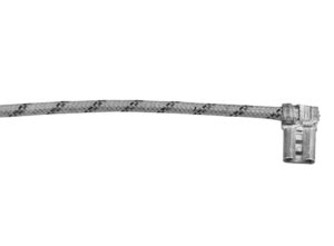
Type QTB: 1/4" Female Right-Angle Quick Disconnect
Various types of crimp terminals can be attached to the heater leads to make wiring into applications quick and easy. Non-insulated and insulated with nylon (221°F/105°C) or PVC (194°F/90°C).
Type QTB: 1/4" Female Right-Angle Quick Disconnect
Various types of crimp terminals can be attached to the heater leads to make wiring into applications quick and easy. Non-insulated and insulated with nylon (221°F/105°C) or PVC (194°F/90°C).
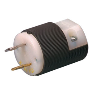
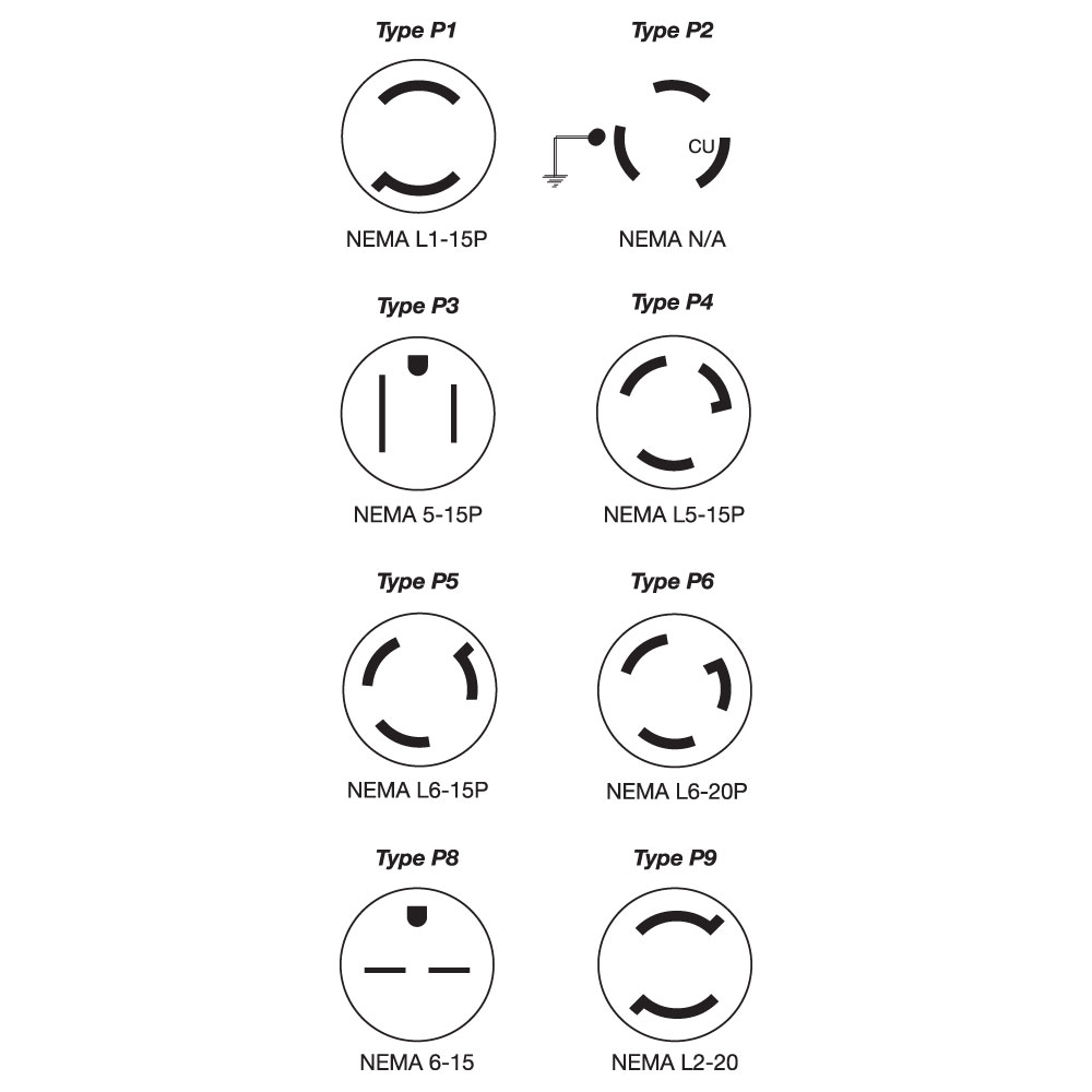
Type P: Quick Disconnect Plugs
Allows for the quick and easy replacement of the heater. The plug can be attached to galvanized armor cable, stainless steel armor cable, or wire braid.
Allows for the quick and easy replacement of the heater. The plug can be attached to galvanized armor cable, stainless steel armor cable, or wire braid.
Plug Type
Description
1
2-pole/2-wire twist locking plug, 15 amp 125 volt NEMA L1-15P (Part Number EHD-102-102)
2
2-pole/3-wire twist locking plug, 15 amp 125 volt or 10 amp 250 volt NEMA N/A. (Part Number EHD-102-107)
NOTE: This plug is not listed by UL, and is recommended for replacement use only.
3
2-pole/3-wire straight blade plug, 15 amp 125 volt NEMA 5-15P (Part Number EHD-102-103)
4
2-pole/3-wire twist locking plug, 15 amp 125 volt NEMA L5-15P (Part Number EHD-102-113)
5
2-pole/3-wire twist locking plug, 15 amp 250 volt NEMA L6-15P (Part Number EHD-102-121)
6
2-pole/3-wire twist locking plug, 20 amp 250 volt NEMA L6-20P (Part Number EHD-102-231)
8
2-pole/3-wire straight blade plug, 15 amp 250 volt NEMA 6-15P (Part Number EHD-102-114)
9
2-pole/3-wire twist locking plug, 20 amp 250 volt NEMA L2-20P (Part Number EHD-102-104)
Available through the Hi-Density Cartridge Heater Terminator Program for Same or Next Day Shipping
Scroll for more
📦
Type MIL: High Temperature Lead Wire
When required, high temperature lead wire can be used on most cartridge heaters. The stranded wire is insulated with mica tapes and then a treated fiberglass overbraid.Maximum temperature rating: 450°C (842°F)
When required, high temperature lead wire can be used on most cartridge heaters. The stranded wire is insulated with mica tapes and then a treated fiberglass overbraid.Maximum temperature rating: 450°C (842°F)
Either the galvanized or stainless steel armor cable can be covered with moisture proof heat shrink Polyolefin tubing.
📦
Type HTL: Very High Temperature Lead Wire
When required, high temperature lead wire can be used on most cartridge heaters. The stranded wire is insulated with mica composite and then a treated fiberglass overbraid. Available wire gauge sizes: 10-18 Maximum temperature rating: 550°C (1022°F)
When required, high temperature lead wire can be used on most cartridge heaters. The stranded wire is insulated with mica composite and then a treated fiberglass overbraid. Available wire gauge sizes: 10-18 Maximum temperature rating: 550°C (1022°F)
📦
Type FS: Uncoated Fiberglass Sleeving
For effective thermal and mechanical protection, the lead wires can be covered with uncoated fiberglass sleeving.
FSA: Uncoated Fiberglass sleeving on each lead separately
FSB: Uncoated Fiberglass sleeving on both leads together Specify length when ordering. Maximum temperature rating: 1112°F (600°C)
Type SR: Silicone Rubber Coated Fiberglass Sleeving
For added protection, strength, and resistance to various chemicals, the lead wires can be covered with silicone rubber sleeving.
SRA: Silicone rubber coated fiberglass sleeving on each lead separately
SRB: Silicone rubber coated fiberglass sleeving on both leads together Specify length when ordering. Maximum temperature rating: 200°C (392°F)
📦
Request Other Termination Option
If your filter selections do not return your desired results from our standard configurations, please continue to select your Specifications. When you are finished, save your selections in the Wish List (using the button at the right of this page) and follow the steps to submit them to Tempco.
If your filter selections do not return your desired results from our standard configurations, please continue to select your Specifications. When you are finished, save your selections in the Wish List (using the button at the right of this page) and follow the steps to submit them to Tempco.
Sheath Options
No options available for this section based on your selections
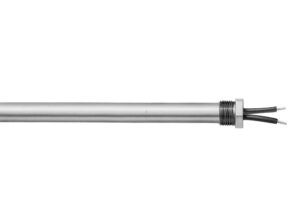
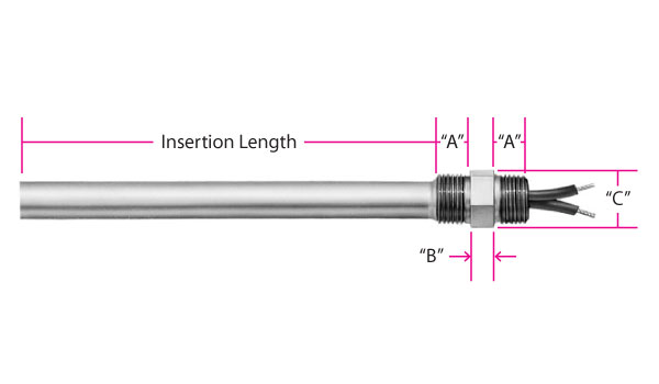
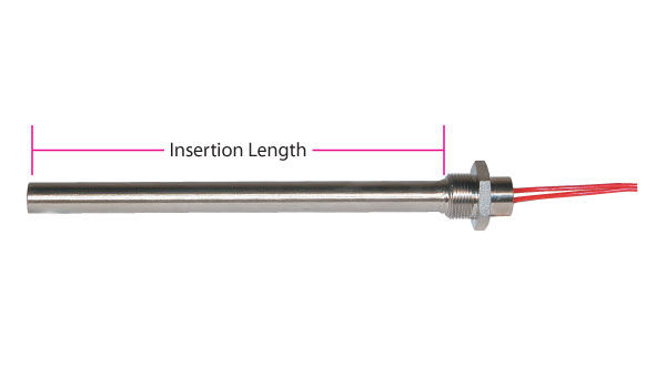
Type CM: Single Threaded Fitting
A single threaded pipe fitting is attached to the end of a cartridge heater to allow for installation into a threaded hole. This mounting option, available with many terminations, can also be offset from the lead end of the sheath. This option is useful when the lead wires need to be kept away from the heated area. Brass fittings are silver brazed and stainless steel fittings are heli-arc welded. Available with the potting seals listed in the table.
A single threaded pipe fitting is attached to the end of a cartridge heater to allow for installation into a threaded hole. This mounting option, available with many terminations, can also be offset from the lead end of the sheath. This option is useful when the lead wires need to be kept away from the heated area. Brass fittings are silver brazed and stainless steel fittings are heli-arc welded. Available with the potting seals listed in the table.
CMA/CMN: Low temperature epoxy potting — 266°F (130°C), UL rated to 194°F (90°C)
Teflon® leads internally connected, rated 392°F (200°C).
CMD/CMR: High temperature epoxy potting — 450°F (232°C)
Teflon® leads internally connected, rated 392°F (200°C).
CMV: Brass Fitting
CMW: Stainless Steel Fitting
A minimum of 1/4″ cold section below the bushing is required.
Standard 10″ (254 mm) leads. Specify longer leads.
Specify offset dimension “E” when ordering.
A termination must be specified separately.
CMB & CMP are available through the Hi-Density Cartridge Heater Terminator Program for 2nd or 3rd Day Shipping.
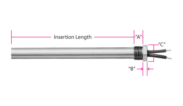
Standard NPT Bushing Dimensions
(Fig. 1 & Fig. 2)
Heater Diameter
NPT
(in)
Size
“A”
“B”
“C”
1/4
1⁄8-27
3/8
3/16
7/16
3/8
1⁄4-18
1/2
3/16
9/16
1/2
3⁄8-18
9/16
1/4
11/16
5/8
1⁄2-14
5/8
1/4
7/8
3/4
3⁄4-14
3/4
1/4
1-1/8
7/8
1-111⁄2
3/4
1/4
1-3/8
1
1-111⁄2
7/8
3/8
1-3/8
1-1/4
11⁄4-111⁄2
15/16
3/8
1-3/4
Scroll for more
Type Codes for Single Threaded Fittings
Fitting Material
Potting Seal Type
Brass
Stainless Steel
Low Temp Epoxy
CMA
CMN
Hi-Temp Cement
CMB
CMP
Silicone Rubber
CMC
CMQ
Hi-Temp Epoxy
CMD
CMR
Scroll for more
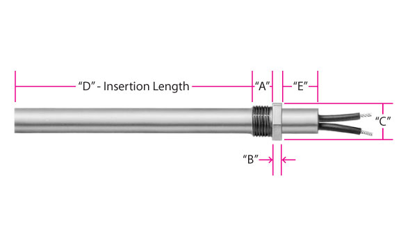
Fitting can be offset from end of sheath. See Figure 2.
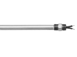
Type CN: Double Threaded Fitting
A double threaded pipe fitting is attached to the end of a cartridge heater to allow for installation into a threaded hole. Brass fittings are silver brazed and stainless steel fittings are heli-arc welded.
A double threaded pipe fitting is attached to the end of a cartridge heater to allow for installation into a threaded hole. Brass fittings are silver brazed and stainless steel fittings are heli-arc welded.
Potted end seals help to protect the heater from moisture or contamination from plastic material, cleaning solvents, or oils. The bushing cavity can be sealed with various materials such as:
CNA/CNN: Low temperature epoxy potting — 266°F (130°C), UL rated to 194°F (90°C)
Teflon® leads internally connected, rated 392°F (200°C).
Standard 10″ (254 mm) leads. Specify longer leads.
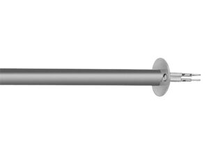
Type MFR: Mounting Flange|Round
Recommended for applications where excessive vibration exists and may cause the heater to back out of its mounting hole. The 16 ga. 304 SS flange is used as a means of securing the cartridge heater in place. The default position of the flange is flush with the lead end. Specify the position of the flange when ordering.
Recommended for applications where excessive vibration exists and may cause the heater to back out of its mounting hole. The 16 ga. 304 SS flange is used as a means of securing the cartridge heater in place. The default position of the flange is flush with the lead end. Specify the position of the flange when ordering.
Available through the Hi-Density Cartridge Heater Terminator Program for Same or Next Day Shipping with flush flange only
Custom Mounting Flanges available upon request. Consult Tempco with your requirements.
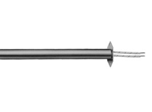
A hex shape allows the possibility of using a wrench when removal is tight. The 16 ga. 304 SS flange is used as a means of securing the cartridge heater in place. The default position of the flange is flush with the lead end. Specify the position of the flange when ordering.
A hex shape allows the possibility of using a wrench when removal is tight. The 16 ga. 304 SS flange is used as a means of securing the cartridge heater in place. The default position of the flange is flush with the lead end. Specify the position of the flange when ordering.
Custom Mounting Flanges available upon request. Consult Tempco with your requirements.
Standard Hex Mounting Flanges
Heater Diameter
“F”
“C”
“H”
in
mm
in
mm
in
mm
in
mm
1/4
6.35
1
25.40
3/4
19.05
.144
3.66
5/16
7.94
1
25.40
3/4
19.05
.144
3.66
3/8
9.53
1
25.40
3/4
19.05
.144
3.66
1/2
12.70
1-3/8
34.93
1-5/32
29.37
.187
4.76
5/8
15.88
1-3/8
34.93
1-5/32
29.37
.187
4.76
3/4
19.05
1-3/8
34.93
1-5/32
29.37
.187
4.76
7/8
22.26
1-7/8
47.63
1-9/16
39.69
.203
5.16
1
25.40
1-7/8
47.63
1-9/16
39.69
.203
5.16
1-1/4
31.80
1-7/8
47.63
1-11/16
42.86
.203
5.16
Scroll for more
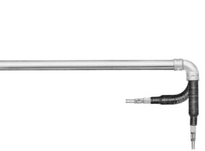
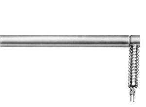
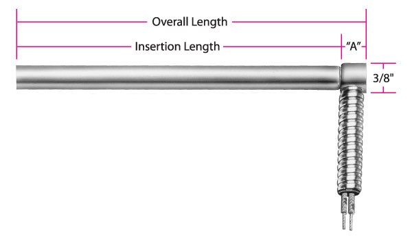
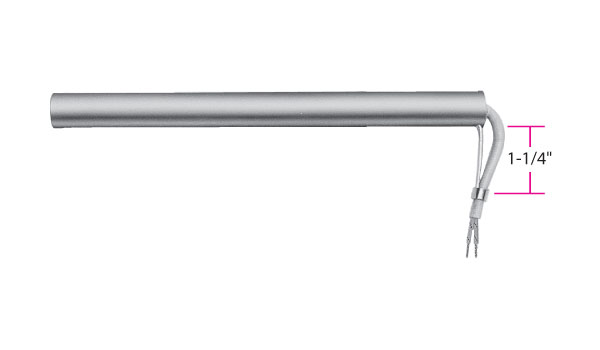
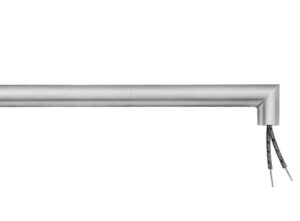
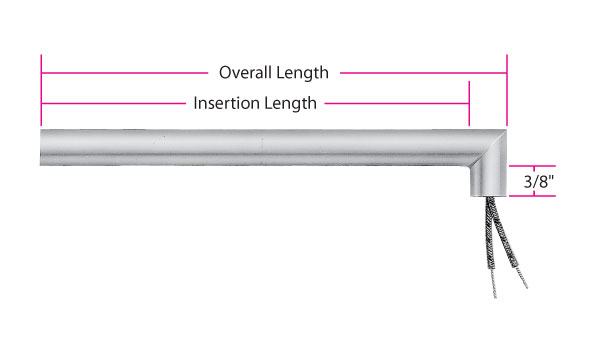
Type R3: Angled Sheath Extension
The sheath extension is welded to the cartridge at a 90° angle. The standard sheath extension is 3/8″ long. Specify when ordering if a longer sheath extension is required. If abrasion resistance is required, armor cable or stainless steel wire braid can be attached to the sheath extension. Available with various lead wire types and potted end seals.
The sheath extension is welded to the cartridge at a 90° angle. The standard sheath extension is 3/8″ long. Specify when ordering if a longer sheath extension is required. If abrasion resistance is required, armor cable or stainless steel wire braid can be attached to the sheath extension. Available with various lead wire types and potted end seals.
Available through the Hi-Density Cartridge Heater Terminator Program for 2nd or 3rd Day Shipping (cement potting only)
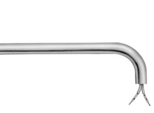
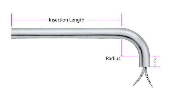
Type R4: Bent Cartridge
The heater sheath itself is bent to 90°. The bend is through a required unheated section. The standard sheath extension past the bend is 1″. Specify when ordering if a longer sheath is required.
The heater sheath itself is bent to 90°. The bend is through a required unheated section. The standard sheath extension past the bend is 1″. Specify when ordering if a longer sheath is required.
*Consult Tempco for Miniature Cartridge Heater Bend Radius details.
Cartridge Dia.
in
1/4
3/8
1/2
5/8
3/4
1
mm
6.35
9.53
12.70
15.88
19.05
25.40
Bend Radius
in
5/8
5/8
3/4
1
1-1/4
1-1/2
mm
15.88
15.88
19.05
25.40
31.75
38.10
Scroll for more
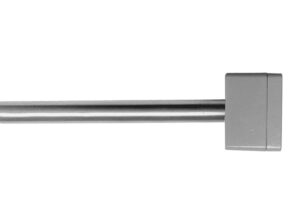
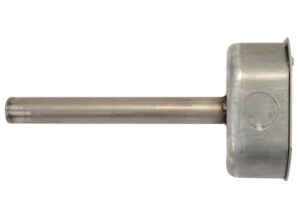
Type LR: Locating Ring
A locating ring can be attached to the heater to aid in positioning the heater for the application. The default position of the ring is 1/4″ from the lead end. Specify the position of the ring when ordering.
A locating ring can be attached to the heater to aid in positioning the heater for the application. The default position of the ring is 1/4″ from the lead end. Specify the position of the ring when ordering.
Available through the Hi-Density Cartridge Heater Terminator Program for Same or Next Day Shipping
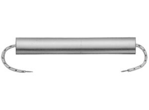
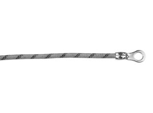
Type PS: Pull Strap
A nickel wire rope is silver brazed to the lead end of the cartridge heater sheath to assist in removing the heater.
A nickel wire rope is silver brazed to the lead end of the cartridge heater sheath to assist in removing the heater.
Available through the Hi-Density Cartridge Heater Terminator Program for Same or Next Day Shipping
📦
Type IS: Incoloy Sheath
The standard sheath material for all Hi-Density Cartridge Heaters except 1″ diameter is 321 stainless steel; standard for 1″ diameter is 304 stainless steel. The incoloy sheath option is available on all diameters except 1/8″, 5/16″, 8 mm and 20 mm. To assist you in selecting the proper sheath material, corrosion resistant ratings and chemical properties of various heater sheath materials are given in the Engineering Section of the site.
The standard sheath material for all Hi-Density Cartridge Heaters except 1″ diameter is 321 stainless steel; standard for 1″ diameter is 304 stainless steel. The incoloy sheath option is available on all diameters except 1/8″, 5/16″, 8 mm and 20 mm. To assist you in selecting the proper sheath material, corrosion resistant ratings and chemical properties of various heater sheath materials are given in the Engineering Section of the site.
📦
Type DSM: Other Special Sheath Materials
If your application requires a specific alloy sheath material, consult Tempco with your requirements.
If your application requires a specific alloy sheath material, consult Tempco with your requirements.
📦
Type PAS: Passivation
Passivating is a chemical process accomplished by dipping the heater in a solution of nitric acid. The process removes surface contamination, usually iron, so that the optimum corrosion resistance of the stainless steel is maintained.
Passivating is a chemical process accomplished by dipping the heater in a solution of nitric acid. The process removes surface contamination, usually iron, so that the optimum corrosion resistance of the stainless steel is maintained.
📦
Type OAL: Special Length Tolerances
If a special length tolerance different than the standard length tolerance specified on page 2-4 is required, consult Tempco with your requirements.
If a special length tolerance different than the standard length tolerance specified on page 2-4 is required, consult Tempco with your requirements.
📦
Type ELP: Electro-Polish
Electro-Polishing is an electro-chemical process that removes surface imperfections and contaminants, enhancing the corrosion resisting ability of the heater sheath.
Electro-Polishing is an electro-chemical process that removes surface imperfections and contaminants, enhancing the corrosion resisting ability of the heater sheath.
📦
Type CG: Centerless Grinding
For applications requiring high precision fit and tolerance, the sheath can be centerless ground. Tolerance: ±0.0005 inches (0.013 mm) Specify diameter when ordering.
For applications requiring high precision fit and tolerance, the sheath can be centerless ground. Tolerance: ±0.0005 inches (0.013 mm) Specify diameter when ordering.
Sensor Options
No options available for this section based on your selections
Type TJ1 and TK1: Grounded at Disc End
The thermocouple junction is grounded to the sheath at the disc end and packed with MgO. The concave end disc is filled with silver solder and ground flat. When inserted into a flat end blind hole, it will provide fast responsive temperature readings. Widely used in Hot Runner mold probes.
The thermocouple junction is grounded to the sheath at the disc end and packed with MgO. The concave end disc is filled with silver solder and ground flat. When inserted into a flat end blind hole, it will provide fast responsive temperature readings. Widely used in Hot Runner mold probes.
TJ1 Type J thermocouple
TK1 Type K thermocouple
Minimum sheath length: 3″ for 1/4″, 3/8″ and 1/2″ diameter. 4″ for 5/8″ and 3/4″ diameter.
10″ leads are standard for both heater and
thermocouple. Leads are internally connected. Specify longer leads.
ANSI Code
Conductor Characteristics
Temperature Ranged
Postivie
Negative
°F
°C
J
Iron (Magnetic)
Constantan (Non-Magnetic)
0 to 1400
-17 to 760
K
Chrome (Non-Magnetic)_
Alumel (Magnetic)
0 to 2300
-17 to 1260
For other thermocouple types, constult Tempco.
Scroll for more
Minimum sheath length: 3″ for 1/4″, 3/8″ and1/2″ diameter. 4″ for 5/8″ and 3/4″ diameter.
Type TJ2 and TK2: Ungrounded at Disc End
The thermocouple junction is ungrounded, located at the end of the heater section, 1/8″ behind the end disc and packed with MgO. Only provides reference temperature reading of the part being heated – slower response.
The thermocouple junction is ungrounded, located at the end of the heater section, 1/8″ behind the end disc and packed with MgO. Only provides reference temperature reading of the part being heated – slower response.
TJ2 Type J thermocouple
TK2 Type K thermocouple
Minimum sheath length: 3″ for 1/4″, 3/8″ and 1/2″ diameter. 4″ for 5/8″ and 3/4″ diameter.
10″ leads are standard for both heater and
thermocouple. Leads are internally connected. Specify longer leads.
ANSI Code
Conductor Characteristics
Temperature Ranged
Postivie
Negative
°F
°C
J
Iron (Magnetic)
Constantan (Non-Magnetic)
0 to 1400
-17 to 760
K
Chrome (Non-Magnetic)_
Alumel (Magnetic)
0 to 2300
-17 to 1260
For other thermocouple types, constult Tempco.
Scroll for more
Minimum sheath length: 3″ for 1/4″, 3/8″ and1/2″ diameter. 4″ for 5/8″ and 3/4″ diameter.
Type TJ3 and TK3: Ungrounded at Center
The thermocouple junction is ungrounded and is located in the center of the length and diameter of the cartridge heater. It provides internal temperature readings of the heater core. Generally used for research applications and is not recommended for controlling process temperatures.
The thermocouple junction is ungrounded and is located in the center of the length and diameter of the cartridge heater. It provides internal temperature readings of the heater core. Generally used for research applications and is not recommended for controlling process temperatures.
TJ3 Type J thermocouple
TK3 Type K thermocouple
Minimum sheath length: 3″ for 1/4″, 3/8″ and 1/2″ diameter. 4″ for 5/8″ and 3/4″ diameter.
10″ leads are standard for both heater and
thermocouple. Leads are internally connected. Specify longer leads.
ANSI Code
Conductor Characteristics
Temperature Ranged
Postivie
Negative
°F
°C
J
Iron (Magnetic)
Constantan (Non-Magnetic)
0 to 1400
-17 to 760
K
Chrome (Non-Magnetic)_
Alumel (Magnetic)
0 to 2300
-17 to 1260
For other thermocouple types, constult Tempco.
Scroll for more
Minimum sheath length: 3″ for 1/4″, 3/8″ and1/2″ diameter. 4″ for 5/8″ and 3/4″ diameter.
Type TJ4 and TK4: Grounded at Center
The thermocouple junction is grounded to the sheath in a 1/2″ unheated section located in the center of the cartridge length unless otherwise specified. It provides good temperature readings with quick response.
The thermocouple junction is grounded to the sheath in a 1/2″ unheated section located in the center of the cartridge length unless otherwise specified. It provides good temperature readings with quick response.
TJ4 Type J thermocouple
TK4 Type K thermocouple
Minimum sheath length: 3″ for 1/4″, 3/8″ and 1/2″ diameter. 4″ for 5/8″ and 3/4″ diameter.
10″ leads are standard for both heater and
thermocouple. Leads are internally connected. Specify longer leads.
ANSI Code
Conductor Characteristics
Temperature Ranged
Postivie
Negative
°F
°C
J
Iron (Magnetic)
Constantan (Non-Magnetic)
0 to 1400
-17 to 760
K
Chrome (Non-Magnetic)_
Alumel (Magnetic)
0 to 2300
-17 to 1260
For other thermocouple types, constult Tempco.
Scroll for more
Minimum sheath length: 3″ for 1/4″, 3/8″ and1/2″ diameter. 4″ for 5/8″ and 3/4″ diameter.
Type TJ5 and TK5: Grounded at Lead End
The thermocouple junction is grounded to the sheath at the lead end. A minimum of 3/8″ of cold section is required. It provides good temperature readings with quick response.
The thermocouple junction is grounded to the sheath at the lead end. A minimum of 3/8″ of cold section is required. It provides good temperature readings with quick response.
TJ5 Type J thermocouple
TK5 Type K thermocouple
Minimum sheath length: 3″ for 1/4″, 3/8″ and 1/2″ diameter. 4″ for 5/8″ and 3/4″ diameter.
10″ leads are standard for both heater and
thermocouple. Leads are internally connected. Specify longer leads.
Note: For a complete selection of standard heaters with built-in Type J thermocouple for Hot Runner, please see the Pennybottom Cartridge Heater Section
ANSI Code
Conductor Characteristics
Temperature Ranged
Postivie
Negative
°F
°C
J
Iron (Magnetic)
Constantan (Non-Magnetic)
0 to 1400
-17 to 760
K
Chrome (Non-Magnetic)_
Alumel (Magnetic)
0 to 2300
-17 to 1260
For other thermocouple types, constult Tempco.
Scroll for more
Minimum sheath length: 3″ for 1/4″, 3/8″ and1/2″ diameter. 4″ for 5/8″ and 3/4″ diameter.
Power Variations
No options available for this section based on your selections
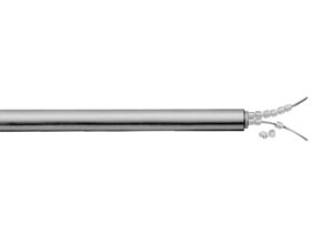
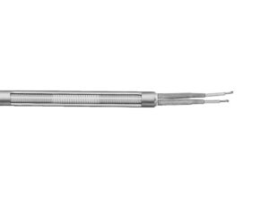
Type DW: Distributed Wattage
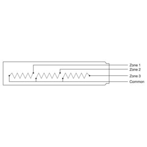
Cartridge heaters can be designed to vary the wattage along the length of the heater. Specify number of zones and the required watts and length per zone starting from the disk end. Leads can be connected externally or internally. Picture shows a heater with Type N externally connected leads. Heaters with other terminations may require a longer cold section at the lead end.
Cartridge heaters can be designed to vary the wattage along the length of the heater. Specify number of zones and the required watts and length per zone starting from the disk end. Leads can be connected externally or internally. Picture shows a heater with Type N externally connected leads. Heaters with other terminations may require a longer cold section at the lead end.
Type 3PH: Three Phase
In order to minimize the gauge of the wiring on high wattage cartridge heaters, 3-phase elements can be designed.
In order to minimize the gauge of the wiring on high wattage cartridge heaters, 3-phase elements can be designed.
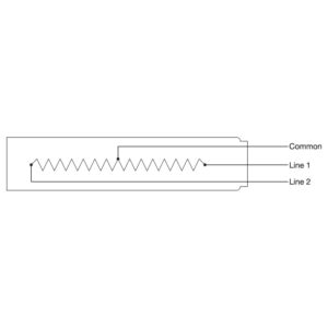
Type DV: Dual Voltage
3/8″ and 1/2″ diameter heaters may require a larger diameter transition area at lead end. Cartridge heaters can be designed using 3-wire series/parallel circuits for dual voltage applications. Whether the heater is run on the high or low voltage, the wattage will be the same. DV1 120/240 volts DV2 240/480 volts
3/8″ and 1/2″ diameter heaters may require a larger diameter transition area at lead end. Cartridge heaters can be designed using 3-wire series/parallel circuits for dual voltage applications. Whether the heater is run on the high or low voltage, the wattage will be the same. DV1 120/240 volts DV2 240/480 volts
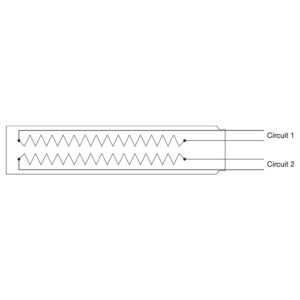
Type DWV: Dual Circuits
Independent resistance elements can be designed in a single cartridge heater for added versatility
Independent resistance elements can be designed in a single cartridge heater for added versatility
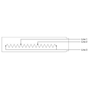
Type MHZ: Multiple Heat Zones
3/8″ and 1/2″ diameter heaters may require a larger diameter transition area at lead end. Multiple independently operated sections of the heater with a common wiring connection can be designed for increased flexibility.
3/8″ and 1/2″ diameter heaters may require a larger diameter transition area at lead end. Multiple independently operated sections of the heater with a common wiring connection can be designed for increased flexibility.
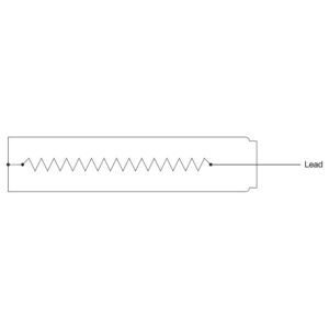
Type GJ: Grounded Element Winding
For DC applications where the electrical circuit is negative grounded, the cartridge heater can be designed with one side of the element winding grounded to the sheath and a single lead wire exiting the cartridge heater.
For DC applications where the electrical circuit is negative grounded, the cartridge heater can be designed with one side of the element winding grounded to the sheath and a single lead wire exiting the cartridge heater.
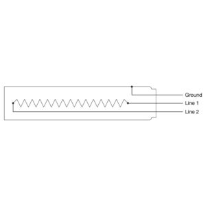
Type GL: Ground Lead/Sheath
For those applications requiring a separate ground lead attached to the cartridge heater sheath. Standard ground lead wire is a 10″ long insulated stranded conductor. Optional insulated and color coded leads are available.
For those applications requiring a separate ground lead attached to the cartridge heater sheath. Standard ground lead wire is a 10″ long insulated stranded conductor. Optional insulated and color coded leads are available.
Available through the Hi-Density Cartridge Heater Terminator Program for 2nd Day Delivery
Additional Options
No options available for this section based on your selections
📦
Type TF: Thermal Fuses
Thermal fuses can be built into cartridge heaters to act as a high limit for the heater in applications where the temperature must be limited to avoid dangerous situations. When the trigger point is reached, the thermal fuse will open, cutting the electrical current to the cartridge heater. Once the thermal fuse opens, it cannot be reset. Many different trigger temperatures are available.
Thermal fuses can be built into cartridge heaters to act as a high limit for the heater in applications where the temperature must be limited to avoid dangerous situations. When the trigger point is reached, the thermal fuse will open, cutting the electrical current to the cartridge heater. Once the thermal fuse opens, it cannot be reset. Many different trigger temperatures are available.
📦
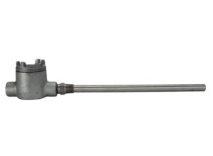
Type TS: Thermostat
Cartridge heaters with built-in thermostats are very efficient and economical for heating and controlling temperatures. Available with NPT or special type mounting fittings, they provide a self-contained heater mainly recommended for immersion applications. They can also be used as over-temperature safety devices. The thermostats are factory preset for the trip temperature; therefore, prototyping and testing is required to determine the exact fixed setpoint. Maximum temperature—302°F (150°C). Maximum Amps—8@120 Volts. A minimum 2-1/2″ cold section is required to house the thermostat. Consult Tempco with your requirements.
Cartridge heaters with built-in thermostats are very efficient and economical for heating and controlling temperatures. Available with NPT or special type mounting fittings, they provide a self-contained heater mainly recommended for immersion applications. They can also be used as over-temperature safety devices. The thermostats are factory preset for the trip temperature; therefore, prototyping and testing is required to determine the exact fixed setpoint. Maximum temperature—302°F (150°C). Maximum Amps—8@120 Volts. A minimum 2-1/2″ cold section is required to house the thermostat. Consult Tempco with your requirements.
📦
Type TM: Thermistor
Tempco has the ability to custom design cartridge heaters with built-in temperature sensors such as thermistors and RTDs. For specific applications that have a limited or single set point range, thermistors or RTDs in conjunction with simple electronic controllers can be an economical choice. NOTE: For thermocouples see page 2-58.
Tempco has the ability to custom design cartridge heaters with built-in temperature sensors such as thermistors and RTDs. For specific applications that have a limited or single set point range, thermistors or RTDs in conjunction with simple electronic controllers can be an economical choice. NOTE: For thermocouples see page 2-58.
📦
Type RD: RTD Temperature Sensor
Tempco has the ability to custom design cartridge heaters with built-in temperature sensors such as thermistors and RTDs. For specific applications that have a limited or single set point range, thermistors or RTDs in conjunction with simple electronic controllers can be an economical choice. NOTE: For thermocouples see page 2-58.
Tempco has the ability to custom design cartridge heaters with built-in temperature sensors such as thermistors and RTDs. For specific applications that have a limited or single set point range, thermistors or RTDs in conjunction with simple electronic controllers can be an economical choice. NOTE: For thermocouples see page 2-58.
📦
Standard Electrical Tests & Optional Test Reports
Standard Electrical Tests and Optional Test Reports 1. Resistance test — measures ohms at room temperature. 2. IR (insulation resistance) test — measures the insulation resistance to the flow of current. Standard test is done at 500VDC. 3. Hipot (high potential) test — a high voltage is applied between a product’s current carrying conductors and its metallic enclosure to verify that the insulation is sufficient to protect the operator from electrical shock. 4. Leakage current test — measures the current that flows from any conductive part to ground. 5. Heaters can be serialized and test reports can be sent with each shipment if required. Contact Tempco with your requirements.
Standard Electrical Tests and Optional Test Reports 1. Resistance test — measures ohms at room temperature. 2. IR (insulation resistance) test — measures the insulation resistance to the flow of current. Standard test is done at 500VDC. 3. Hipot (high potential) test — a high voltage is applied between a product’s current carrying conductors and its metallic enclosure to verify that the insulation is sufficient to protect the operator from electrical shock. 4. Leakage current test — measures the current that flows from any conductive part to ground. 5. Heaters can be serialized and test reports can be sent with each shipment if required. Contact Tempco with your requirements.
📦
Die Penetrant Test
This non-destructive testing can detect imperfections in weld joints. For critical applications, each individual heater’s weld joints by end cap and fittings can be tested. Certified test reports will be sent with each shipment. Consult Tempco for details.
This non-destructive testing can detect imperfections in weld joints. For critical applications, each individual heater’s weld joints by end cap and fittings can be tested. Certified test reports will be sent with each shipment. Consult Tempco for details.
📦
Hydrostatic Pressure Test
Cartridge heaters with attached pipe fittings can be pressure tested to your specifications at Tempco. Our in-house testing capabilities can ensure that your products meet your exact specifications. Contact Tempco with your requirements.
Cartridge heaters with attached pipe fittings can be pressure tested to your specifications at Tempco. Our in-house testing capabilities can ensure that your products meet your exact specifications. Contact Tempco with your requirements.
Type W3: Swaged-In Wire Braided Leads Stainless steel braid over fiberglass leads offers sharp bending not possible with armor cable, as well as abrasion protection. In addition, Type W3 offers contamination resistance due to the Teflon® seal required for holding the wire braid. Minimum 3/8″ up to 1″ unheated section at the lead end is required. Teflon® Seal temperature rating: 392°F (200°C) Standard lead wire temperature rating: 842°F (450°C) Standard 10″ (254 mm) braid over 12″ (305 mm) leads. Specify longer braid/leads. Electrical Terminations 10 mm 12.5 mm 16 mm 20 mm 6.5 mm 8 mm Additional Options Grounded Grounding Heat Zones Heater Diameter (if known) Heater Removal Inspection & Testing Lead Wire Options Material Options Mounting Options Not Available Power Formations Power Variations Quick Disconnect Plugs Right Angle Options Sensor & Control Options Sensor Options Sheath Options Single-End, Straight Terminal Housings Termination Location Termination Options Terminator Program Tolerance Options Ungrounded Wire Braids Type W1: Right-Angle Wire Braided Leads Stainless steel braid over fiberglass leads for abrasion protection, mechanically crimped to the cartridge sheath at 90°. Wire braid offers extreme flexibility not possible with armor cable. Various lead end finishes are available as listed below. W1A: Cement potting and silicone varnish, no lead end disc. Cement potting temperature rating: 1000°F (538°C) Standard lead wire temperature rating: 482°F (250°C) W1B: Welded lead end disc. Cement potting temperature rating: 1000°F (538°C) Standard lead wire temperature rating: 482°F (250°C) Minimum 3/8″ up to 1″ unheated section at the lead end is required. Standard 10″ (254 mm) braid over 12″ (305 mm) leads. Specify longer braid or leads. Single-End, Right-Angle Type W: Wire Braided Leads Stainless steel braid over fiberglass leads offers sharp bending not possible with armor cable, as well as abrasion protection. Minimum 3/8″ up to 1″ unheated section at the lead end is required. Standard lead wire temperature rating for standard HDC and HDM: 842°F (450°C) Standard fiberglass lead wire temperature rating for LDC: 482°F (250°C) Standard 10″ (254 mm) braid over 12″ (305 mm) leads. Specify longer braid/leads Available through the Hi-Density Cartridge Heater Terminator Program for 2nd or 3rd Day Shipping *Consult Tempco for Miniature Cartridge Heater dimensions for Type W. Type TS: Thermostat Cartridge heaters with built-in thermostats are very efficient and economical for heating and controlling temperatures. Available with NPT or special type mounting fittings, they provide a self-contained heater mainly recommended for immersion applications. They can also be used as over-temperature safety devices. The thermostats are factory preset for the trip temperature; therefore, prototyping and testing is required to determine the exact fixed setpoint. Maximum temperature—302°F (150°C). Maximum Amps—8@120 Volts. A minimum 2-1/2″ cold section is required to house the thermostat. Consult Tempco with your requirements. Armor Cable Double-Ended Flexible Spring Protected Leads High Temperature Moisture Resistant Leads Plain Lead Wires Terminals Type TM: Thermistor Tempco has the ability to custom design cartridge heaters with built-in temperature sensors such as thermistors and RTDs. For specific applications that have a limited or single set point range, thermistors or RTDs in conjunction with simple electronic controllers can be an economical choice. NOTE: For thermocouples see page 2-58. Type TL: Teflon® Leads Maximum temperature rating: 200°C (392°F) Type TJ5 and TK5: Grounded at Lead End The thermocouple junction is grounded to the sheath at the lead end. A minimum of 3/8″ of cold section is required. It provides good temperature readings with quick response. TJ5 Type J thermocouple TK5 Type K thermocouple Minimum sheath length: 3″ for 1/4″, 3/8″ and 1/2″ diameter. 4″ for 5/8″ and 3/4″ diameter. 10″ leads are standard for both heater and thermocouple. Leads are internally connected. Specify longer leads. Note: For a complete selection of standard heaters with built-in Type J thermocouple for Hot Runner, please see the Pennybottom Cartridge Heater Section Minimum sheath length: 3" for 1/4", 3/8" and1/2" diameter. 4" for 5/8" and 3/4" diameter. Type TJ4 and TK4: Grounded at Center The thermocouple junction is grounded to the sheath in a 1/2″ unheated section located in the center of the cartridge length unless otherwise specified. It provides good temperature readings with quick response. TJ4 Type J thermocouple TK4 Type K thermocouple Minimum sheath length: 3″ for 1/4″, 3/8″ and 1/2″ diameter. 4″ for 5/8″ and 3/4″ diameter. 10″ leads are standard for both heater and thermocouple. Leads are internally connected. Specify longer leads. Type TJ3 and TK3: Ungrounded at Center The thermocouple junction is ungrounded and is located in the center of the length and diameter of the cartridge heater. It provides internal temperature readings of the heater core. Generally used for research applications and is not recommended for controlling process temperatures. TJ3 Type J thermocouple TK3 Type K thermocouple Minimum sheath length: 3″ for 1/4″, 3/8″ and 1/2″ diameter. 4″ for 5/8″ and 3/4″ diameter. 10″ leads are standard for both heater and thermocouple. Leads are internally connected. Specify longer leads. Type TJ2 and TK2: Ungrounded at Disc End The thermocouple junction is ungrounded, located at the end of the heater section, 1/8″ behind the end disc and packed with MgO. Only provides reference temperature reading of the part being heated – slower response. TJ2 Type J thermocouple TK2 Type K thermocouple Minimum sheath length: 3″ for 1/4″, 3/8″ and 1/2″ diameter. 4″ for 5/8″ and 3/4″ diameter. 10″ leads are standard for both heater and thermocouple. Leads are internally connected. Specify longer leads. Type TJ1 and TK1: Grounded at Disc End The thermocouple junction is grounded to the sheath at the disc end and packed with MgO. The concave end disc is filled with silver solder and ground flat. When inserted into a flat end blind hole, it will provide fast responsive temperature readings. Widely used in Hot Runner mold probes. TJ1 Type J thermocouple TK1 Type K thermocouple Minimum sheath length: 3″ for 1/4″, 3/8″ and 1/2″ diameter. 4″ for 5/8″ and 3/4″ diameter. 10″ leads are standard for both heater and thermocouple. Leads are internally connected. Specify longer leads. Type TF: Thermal Fuses Thermal fuses can be built into cartridge heaters to act as a high limit for the heater in applications where the temperature must be limited to avoid dangerous situations. When the trigger point is reached, the thermal fuse will open, cutting the electrical current to the cartridge heater. Once the thermal fuse opens, it cannot be reset. Many different trigger temperatures are available. Type TH: Top Hat Screw Plug This heater has a header cap as an integral part of the fitting. Leads exit through small holes which are sealed with epoxy for moisture protection. Low temperature epoxy potting — 266°F (130°C), UL rated to 194°F (90°C) Teflon® leads internally connected, rated 392°F (200°C). Standard 10″ (254 mm) leads. Specify longer leads. Type T4: Double-End Terminal Pin For those applications in which wiring from both ends is an advantage. Various seals are available: T4A: Cement potting seal with silicone varnish Cement potting temperature rating: 1000°F (538°C) T4B: High temp. moisture resistant epoxy seal High temp. epoxy temp. rating: 450°F (232°C) T4C: Low temp. moisture resistant epoxy seal Low temp. epoxy temp. rating: 266°F (130°C) Minimum 1″ unheated section at each end is required. Standard terminal pin length is 2″. Type T3: Double-End Screw Terminal Leads A Double-Ended heater with quick change wiring screw terminals. Includes zinc plated washers and nuts. Minimum 1/2″ unheated section at each end is required. Standard screw sizes: 1/2″ diameter – #8-32 × 3/4″ screws 5/8″ to 1-1/4″ diameter – #10-32 × 3/4″ screws Type T2: Screw Terminals For use with leads, crimp terminals, or bus bars. Includes washers and nuts. Minimum 1/2″ unheated section at the lead end is required. Diameters available: HDC – 5/8″, 3/4″, 1″ HDM – 16 mm and 20 mm Standard: screw #8-32 Type ST: Spade Terminal Various types of crimp terminals can be attached to the heater leads to make wiring into applications quick and easy. Non-insulated and insulated with nylon (221°F/105°C) or PVC (194°F/90°C). Type SR: Silicone Rubber Coated Fiberglass Sleeving For added protection, strength, and resistance to various chemicals, the lead wires can be covered with silicone rubber sleeving. SRA: Silicone rubber coated fiberglass sleeving on each lead separately SRB: Silicone rubber coated fiberglass sleeving on both leads together Specify length when ordering. Maximum temperature rating: 200°C (392°F) Type SA: Sealed Corrugated Armor Cable A liquid-proof stainless steel corrugated metal hose is silver brazed to the end of the cartridge heater. The end disc of the heater is also welded or brazed. This termination provides a positive seal against moisture and contamination entering the heater. Minimum 3/8″ up to 1″ unheated section at the lead end is required. Standard fiberglass lead wire temperature rating for HDC and HDM: 842°F (450°C) Standard fiberglass lead wire temperature rating for LDC: 482°F (250°C) Standard 10″ (254 mm) cable over 12″ (305 mm) leads. Specify longer leads or cable. Type S4: Right-Angle Lead Wire Strain Relief Strain relief clip for leads subject to tension and stress. A “T” type strain relief is silver brazed to the sheath and bent at a 90° angle. Type S1: Flexible Spring The leads are reinforced with a steel spring for applications with extreme flexing. The spring is mechanically fastened or silver brazed. S1A Mechanically fastened spring. S1B Silver brazed spring. Minimum 3/8″ up to 1″ unheated section at the lead end is required. Standard fiberglass lead wire temperature rating for HDC and HDM: 842°F (450°C) Standard fiberglass lead wire temperature rating for LDC: 482°F (250°C) Standard 10″ (254 mm) leads. Specify longer leads. Type S2: Right-Angle Spring S2A: Mechanically fastened spring S2B: Silver brazed spring Minimum 3/8″ up to 1″ unheated section at the lead end is required. Standard fiberglass lead wire temperature rating for HDC and HDM: 842°F (450°C) Standard fiberglass lead wire temperature rating for LDC: 482°F (250°C) Standard 10″ (254 mm) leads. Specify longer leads. Type S3: Lead Wire Strain Relief Strain relief clip for leads subject to tension and stress. A “T” type strain relief is silver brazed to the sheath. Type RT: Ring Terminal Type RD: RTD Temperature Sensor Type R4: Bent Cartridge The heater sheath itself is bent to 90°. The bend is through a required unheated section. The standard sheath extension past the bend is 1″. Specify when ordering if a longer sheath is required. *Consult Tempco for Miniature Cartridge Heater Bend Radius details. Type R3: Angled Sheath Extension The sheath extension is welded to the cartridge at a 90° angle. The standard sheath extension is 3/8″ long. Specify when ordering if a longer sheath extension is required. If abrasion resistance is required, armor cable or stainless steel wire braid can be attached to the sheath extension. Available with various lead wire types and potted end seals. Available through the Hi-Density Cartridge Heater Terminator Program for 2nd or 3rd Day Shipping (cement potting only) Type R2: Right-Angle Leads This termination is used when space is limited. Not suitable for abrasive environments. The plain leads are internally connected and they offer flexibility. Various lead end finishes are available as listed below: R2A: Cement potting, no lead end disc Cement potting temperature rating: 1000°F (538°C) Standard fiberglass lead wire temperature rating: 482°F (250°C) R2B: Cement potting, welded lead end disc Cement potting temperature rating: 1000°F (538°C) Standard fiberglass lead wire temperature rating: 482°F (250°C) R2C: Silicone rubber potting, welded lead end disc Silicone Rubber potting temperature rating: 392°F (200°C) Standard silicone rubber lead wire temperature rating: 392°F (200°C) R2D: High temperature epoxy potting, welded lead end disc High Temperature epoxy potting temperature rating: 450°F (232°C) Standard Teflon® lead wire temperature rating: 392°F (200°C) R2E: Low temperature epoxy potting, welded lead end disc Low Temperature epoxy potting temperature rating: 266°F (130°C) Standard Teflon® lead wire temperature rating: 392°F (200°C) Minimum 3/8″ up to 1″ unheated section at the lead end is required. Standard 10″ (254 mm) leads. Specify other lead lengths. R2A and R2B are available through the Hi-Density Cartridge Heater Terminator Program for 2nd or 3rd Day Shipping Type R1: Right-Angle Leads with Copper Elbow This termination is used when space is limited. The copper elbow is mechanically fastened or silver brazed. R1A: Mechanically fastened R1B: Silver brazed Minimum 3/8″ up to 1″ unheated section at the lead end is required. Standard fiberglass lead wire temperature rating for HDC and HDM: 842°F (450°C) Standard fiberglass lead wire temperature rating for LDC: 482°F (250°C) Standard 10″ (254 mm) leads. Specify longer leads. R1A is available through the Hi-Density Cartridge Heater Terminator Program for Same or Next Day Shipping. Type QTB: 1/4" Female Right-Angle Quick Disconnect Type PAS: Passivation Passivating is a chemical process accomplished by dipping the heater in a solution of nitric acid. The process removes surface contamination, usually iron, so that the optimum corrosion resistance of the stainless steel is maintained. Type PS: Pull Strap A nickel wire rope is silver brazed to the lead end of the cartridge heater sheath to assist in removing the heater. Available through the Hi-Density Cartridge Heater Terminator Program for Same or Next Day Shipping Type QTA: 1/4" Female Straight Quick Disconnect Type P: Quick Disconnect Plugs Allows for the quick and easy replacement of the heater. The plug can be attached to galvanized armor cable, stainless steel armor cable, or wire braid. Type OAL: Special Length Tolerances If a special length tolerance different than the standard length tolerance specified on page 2-4 is required, consult Tempco with your requirements. Type N: External Pins with Leads Standard Termination for Hi-Density and Hi-Density Metric Cartridge Heaters. Flexible stranded lead wires have fiberglass insulation and are connected to 1-1/4″ (32 mm) long solid conductors. Silicone rubber coated fiberglass sleeving insulates the pin/lead wire connection. Nominal 3/8″ unheated section at the lead end is required. Standard lead wire temperature rating: 482°F (250°C) Silicone rubber coated fiberglass sleeving temperature rating: 392°F (200°C) Standard 10″ (254 mm) leads. Specify longer leads. Type MIL: High Temperature Lead Wire When required, high temperature lead wire can be used on most cartridge heaters. The stranded wire is insulated with mica tapes and then a treated fiberglass overbraid.Maximum temperature rating: 450°C (842°F) Type MHZ: Multiple Heat Zones 3/8″ and 1/2″ diameter heaters may require a larger diameter transition area at lead end. Multiple independently operated sections of the heater with a common wiring connection can be designed for increased flexibility. Type MFR: Mounting Flange|Round Recommended for applications where excessive vibration exists and may cause the heater to back out of its mounting hole. The 16 ga. 304 SS flange is used as a means of securing the cartridge heater in place. The default position of the flange is flush with the lead end. Specify the position of the flange when ordering. Available through the Hi-Density Cartridge Heater Terminator Program for Same or Next Day Shipping with flush flange only Custom Mounting Flanges available upon request. Consult Tempco with your requirements. Type MFH: Mounting Flange|Hexagon A hex shape allows the possibility of using a wrench when removal is tight. The 16 ga. 304 SS flange is used as a means of securing the cartridge heater in place. The default position of the flange is flush with the lead end. Specify the position of the flange when ordering. Custom Mounting Flanges available upon request. Consult Tempco with your requirements. Type M3: Teflon® End Plug Seal Standard Termination for Hi-Density Miniature Cartridge Heaters. A moisture resistant Teflon® seal that is swaged in during the manufacturing process with Teflon® insulated lead wire. Minimum 3/8″ up to 1″ unheated section at the lead end is required for most heater sizes. Teflon® seal Temperature rating: 392°F (200°C) Standard lead wire Temperature rating: 392°F (200°C) Standard 10″ (254 mm) leads. Specify longer leads. Leads longer than 60″ require a splice. Type M2: Potted End Seal Potted end seals help to protect the heater from moisture or contamination from plastic material, cleaning solvents, or oils. The bottom end disc seal is welded in. M2A: Cement potting with silicone varnish. Fiberglass lead wires externally connected. Cement potting temperature rating: 1000°F (538°C) Standard lead wire temperature rating: 482°F (250°C) M2B: Silicone rubber potting. Silicone rubber lead wires internally connected. Silicone rubber potting temperature rating: 392°F (200°C) Standard lead wire temperature rating: 392°F (200°C) M2C: High temperature epoxy potting. Teflon® lead wires internally connected. High temp. epoxy potting temp. rating: 450°F (232°C) Standard lead wire temperature rating: 392°F (200°C) M2D: Low temperature epoxy potting. Teflon® lead wires internally connected. Low temp. epoxy potting temp. rating: 266°F (130°C), UL rated to 194°F (90°C) Standard lead wire temperature rating: 392°F (200°C) M2E: Cement potting with silicone varnish. Fiberglass lead wires internally connected. Cement potting temperature rating: 1000°F (538°C) Standard lead wire temperature rating: 482°F (250°C) Minimum of 3/8″ up to 1″ unheated section at the lead end is required. Standard 10″ (254 mm) leads. Specify longer leads. NOTE: M2A and M2E are available through the Hi-Density Cartridge Heater Terminator Program for 2nd or 3rd Day Shipping Type M1: Polyolefin Liquid Barrier A liquid barrier used for low temperature applications primarily in refrigeration or food service applications. The seal bonds to both the heater and the leads. Minimum 1″ unheated section at the lead end is required. Three conductor SJO type cord. Available only in certain diameters. Heaters smaller than 1/2″ diameter require an adapter. Standard 10″ (254 mm) leads. Specify longer leads. Type LR: Locating Ring A locating ring can be attached to the heater to aid in positioning the heater for the application. The default position of the ring is 1/4″ from the lead end. Specify the position of the ring when ordering. Type IS: Incoloy Sheath The standard sheath material for all Hi-Density Cartridge Heaters except 1″ diameter is 321 stainless steel; standard for 1″ diameter is 304 stainless steel. The incoloy sheath option is available on all diameters except 1/8″, 5/16″, 8 mm and 20 mm. To assist you in selecting the proper sheath material, corrosion resistant ratings and chemical properties of various heater sheath materials are given in the Engineering Section of the site. Type HTL: Very High Temperature Lead Wire When required, high temperature lead wire can be used on most cartridge heaters. The stranded wire is insulated with mica composite and then a treated fiberglass overbraid. Available wire gauge sizes: 10-18 Maximum temperature rating: 550°C (1022°F) Type HA: Heat Shrink covered Armor Cables Either the galvanized or stainless steel armor cable can be covered with moisture proof heat shrink Polyolefin tubing. Type FS: Uncoated Fiberglass Sleeving For effective thermal and mechanical protection, the lead wires can be covered with uncoated fiberglass sleeving. FSA: Uncoated Fiberglass sleeving on each lead separately FSB: Uncoated Fiberglass sleeving on both leads together Specify length when ordering. Maximum temperature rating: 1112°F (600°C) Type GJ: Grounded Element Winding For DC applications where the electrical circuit is negative grounded, the cartridge heater can be designed with one side of the element winding grounded to the sheath and a single lead wire exiting the cartridge heater. Type GL: Ground Lead/Sheath For those applications requiring a separate ground lead attached to the cartridge heater sheath. Standard ground lead wire is a 10″ long insulated stranded conductor. Optional insulated and color coded leads are available. Available through the Hi-Density Cartridge Heater Terminator Program for 2nd Day Delivery Type F1: Double-End Flexible Leads For applications in which it is an advantage to wire from both ends. The leads are internally connected and can be bent sharply as they exit the potted ends. Various seals are available: F1A: Fiberglass leads with cement potting seal and silicone varnish Cement potting temperature rating: 1000°F (532°C) Standard lead wire temperature rating: 482°F (250°C) F1B: Teflon® leads with high temp. moisture resistant epoxy seal High temp. epoxy temperature rating: 450°F (232°C) Standard lead wire temperature rating: 392°F (200°C) F1C: Teflon® leads with low temp. moisture resistant epoxy seal Low temp. epoxy temperature rating: 266°F (130°C) Standard lead wire temperature rating: 392°F (200°C) Minimum 1″ unheated section at each end is required. Standard 10″ leads. Specify longer leads. Leads longer than 60″ require a splice. Type F: Internally Connected Flexible Leads Standard Termination for Low-Density Cartridge Heaters. The fiberglass lead wires are internally connected to the terminal pins. This lead termination provides flexibility, permitting the lead wires to be sharply bent as they exit the heater. Minimum 3/8″ up to 1″ unheated section at the lead end is required. Standard lead wire temperature rating for HDC & HDM: 842°F (450°C). Standard lead wire temperature rating for LDC: 482°F (250°C). Standard 10″ (254 mm) leads. Specify longer leads. For HDC & HDM heaters, leads longer than 60″ require a splice. Type ELP: Electro-Polish Electro-Polishing is an electro-chemical process that removes surface imperfections and contaminants, enhancing the corrosion resisting ability of the heater sheath. Type E5: Octagon Terminal Box NEMA 4/7 electrical enclosures provide protection from contaminants, moisture, and hazardous conditions. These housings are screwed onto a heater with a single or double ended Brass or Stainless Steel fitting. A threaded fitting mounting termination must be specified. See pages 2-50 and 2-51. Other terminal box configurations available upon request. Type E4: General Purpose Terminal Box (mailbox style) General purpose steel NEMA 1 electrical enclosure designed to provide protection from electrical shock. The box is welded to the cartridge sheath. A termination must be specified separately. Type E3: Explosion Resistant Terminal Boxes General purpose Stainless Steel NEMA 1 electrical enclosure designed to provide protection from electrical shock. The box is welded or brazed to the cartridge sheath. Type E2: Moisture Proof Terminal Box NEMA 4 aluminum electrical enclosures provide protection from splashing or hose directed water, external condensation and water seepage. The box is mechanically attached to the cartridge sheath. A single 5/8″ access hole is standard. A termination must be specified separately. Type E1: General Purpose Terminal Box General purpose Stainless Steel NEMA 1 electrical enclosure designed to provide protection from electrical shock. The boxes have a 5/8″ conduit knockout and are welded or brazed to the cartridge sheath. A termination must be specified separately. Available through the Hi-Density Cartridge Heater Terminator Program For 2nd or 3rd Day Shipping Type DWV: Dual Circuits Independent resistance elements can be designed in a single cartridge heater for added versatility Type DW: Distributed Wattage Cartridge heaters can be designed to vary the wattage along the length of the heater. Specify number of zones and the required watts and length per zone starting from the disk end. Leads can be connected externally or internally. Picture shows a heater with Type N externally connected leads. Heaters with other terminations may require a longer cold section at the lead end. Type DSM: Other Special Sheath Materials If your application requires a specific alloy sheath material, consult Tempco with your requirements. Type DV: Dual Voltage 3/8″ and 1/2″ diameter heaters may require a larger diameter transition area at lead end. Cartridge heaters can be designed using 3-wire series/parallel circuits for dual voltage applications. Whether the heater is run on the high or low voltage, the wattage will be the same. DV1 120/240 volts DV2 240/480 volts Type CS: Straight Armor Cable Directly Attached to Sheath The armor cable is directly attached to the cartridge heater, eliminating the coupling, to maintain an overall diameter equal to or smaller than the cartridge diameter. Minimum 3/8″ up to 1″ unheated section at the lead end is required. Heaters with an OD of 3/4″ or larger require reducing diameter washer. Standard fiberglass lead wire temperature rating for HDC and HDM: 842°F (450°C) Standard fiberglass lead wire temperature rating for LDC: 482°F (250°C) Standard 10″ (254 mm) cable over 12″ (305 mm) leads. Specify longer leads or cable. Type CN: Double Threaded Fitting A double threaded pipe fitting is attached to the end of a cartridge heater to allow for installation into a threaded hole. Brass fittings are silver brazed and stainless steel fittings are heli-arc welded. Potted end seals help to protect the heater from moisture or contamination from plastic material, cleaning solvents, or oils. The bushing cavity can be sealed with various materials such as: CNA/CNN: Low temperature epoxy potting — 266°F (130°C), UL rated to 194°F (90°C) Teflon® leads internally connected, rated 392°F (200°C). CNB/CNP: Hi-temp cement potting w/ silicone varnish — 1000°F (538°C) Fiberglass leads internally connected, rated 482°F (250°C). CNC/CNQ: Silicone rubber potting — 392°F (200°C) Silicone rubber leads internally connected, rated 392°F (200°C). CND/CNR: High temperature epoxy potting — 450°F (232°C) Teflon® leads internally connected, rated 392°F (200°C). A minimum of 1/4″ cold section below the bushing is required. Standard 10″ (254 mm) leads. Specify longer leads. A termination must be specified separately Type CM: Single Threaded Fitting A single threaded pipe fitting is attached to the end of a cartridge heater to allow for installation into a threaded hole. This mounting option, available with many terminations, can also be offset from the lead end of the sheath. This option is useful when the lead wires need to be kept away from the heated area. Brass fittings are silver brazed and stainless steel fittings are heli-arc welded. Available with the potting seals listed in the table. CMA/CMN: Low temperature epoxy potting — 266°F (130°C), UL rated to 194°F (90°C) Teflon® leads internally connected, rated 392°F (200°C). CMB/CMP: Hi-temp cement potting with silicone varnish — 1000°F (538°C) Fiberglass leads internally connected, rated 482°F (250°C). CMC/CMQ: Silicone rubber potting — 392°F (200°C) Silicone rubber leads internally connected, rated 392°F (200°C). CMD/CMR: High temperature epoxy potting — 450°F (232°C) Teflon® leads internally connected, rated 392°F (200°C). CMV: Brass Fitting CMW: Stainless Steel Fitting A minimum of 1/4″ cold section below the bushing is required. Standard 10″ (254 mm) leads. Specify longer leads. Specify offset dimension “E” when ordering. A termination must be specified separately. CMB & CMP are available through the Hi-Density Cartridge Heater Terminator Program for 2nd or 3rd Day Shipping. Fitting can be offset from end of sheath. See Figure 2. Type CG: Centerless Grinding For applications requiring high precision fit and tolerance, the sheath can be centerless ground. Tolerance: ±0.0005 inches (0.013 mm) Specify diameter when ordering. Type C3: Right-Angle Armor Cable Use this termination when space is limited and maximum protection is required. The armor cable is tack welded or silver brazed to the cartridge sheath at 90°. The sheath extension is potted with cement. Various lead end finishes are available as listed below. C3A: Cement potting and silicone varnish with no lead end disc, galvanized cable C3B: Cement potting and silicone varnish with no lead end disc, stainless steel cable C3C: Welded lead end disc, with galvanized cable C3D: Welded lead end disc, with stainless steel cable Minimum 3/8″ up to 1″ unheated section at the lead end is required. Cement potting temperature rating: 1000°F (538°C) Standard fiberglass lead wire temperature rating: 482°F (250°C) Standard 10″ (254 mm) armor cable over 12″ (305 mm) leads. Specify longer cable or leads. Type C2: Right-Angle Armor Cable with Copper Elbow Armor cable provides the maximum in protection for abrasive, jagged environments. The copper elbow between the cartridge and the armor cable is mechanically fastened or silver brazed. C2A: Galvanized armor cable, mechanically fastened C2B: Stainless steel armor cable, mechanically fastened C2C: Galvanized armor cable, silver brazed C2D: Stainless steel armor cable, silver brazed Minimum 3/8″ up to 1″ unheated section at the lead end is required. Standard fiberglass lead wire temperature rating for HDC and HDM: 842°F (450°C) Standard fiberglass lead wire temperature rating for LDC:482°F (250°C) Standard 10″ (254 mm) cable over 12″ (305 mm) leads. Specify longer cable or leads. C2A and C2B are available through the Hi-Density Cartridge Heater Terminator Program for Same or Next Day Shipping. Type C1: Straight Armor Cable with Coupling Armor cable provides the maximum in protection for abrasive, jagged environments. The coupling between the cartridge and the armor cable is mechanically fastened or silver brazed. *Limited to C1B: SS Cable, Mechanically Fastened for 1/8″ Miniature Cartridge Heaters C1A: Galvanized armor cable, mechanically fastened C1B: Stainless steel armor cable, mechanically fastened Standard lead wire temperature rating: 482°F (250°C) C1C: Galvanized armor cable, silver brazed C1D: Stainless steel armor cable, silver brazed Standard fiberglass lead wire temperature rating for HDC and HDM: 842°F (450°C) Standard fiberglass lead wire temperature rating for LDC: 482°F (250°C) Minimum 3/8″ up to 1″ unheated section at the lead end is required. Standard 10″ (254 mm) cable over 12″ (305 mm) leads. Specify longer leads or cable. Type BL: Heat Resistant Ceramic Bead Insulation with Leads High temperature flexible leads are connected away from the high heat area. Standard 6″ (254 mm) solid nickel pins insulated with ball and socket construction type ceramic beads and 10″ (254 mm) fiberglass leads rated at 842°F (450°C). Specify longer leads. Available through the Hi-Density Cartridge Heater Terminator Program for Same or Next Day Shipping. Type B: Heat Resistant Ceramic Bead Insulation The ultimate in high temperature lead protection. Allows for the attachment of flexible leads to the heater away from the high heat area. Used when the ambient temperature exceeds 842°F (450°C). Standard 10″ (254 mm) solid nickel pins insulated with ball and socket construction type ceramic beads. Available through the Hi-Density Cartridge Heater Terminator Program for Same or Next Day Shipping. Type 3PH: Three Phase In order to minimize the gauge of the wiring on high wattage cartridge heaters, 3-phase elements can be designed. Standard Electrical Tests & Optional Test Reports Standard Electrical Tests and Optional Test Reports 1. Resistance test — measures ohms at room temperature. 2. IR (insulation resistance) test — measures the insulation resistance to the flow of current. Standard test is done at 500VDC. 3. Hipot (high potential) test — a high voltage is applied between a product’s current carrying conductors and its metallic enclosure to verify that the insulation is sufficient to protect the operator from electrical shock. 4. Leakage current test — measures the current that flows from any conductive part to ground. 5. Heaters can be serialized and test reports can be sent with each shipment if required. Contact Tempco with your requirements. Single-Ended Straight Termination The Electrical Termination is located at one end of the heater and exits straight out from the heater. Single-Ended Right-Angle Termination The Electrical Termination is located at one end of the heater and exits at a right angle from the heater. Request Other Termination Option If your filter selections do not return your desired results from our standard configurations, please continue to select your Specifications. When you are finished, save your selections in the Wish List (using the button at the right of this page) and follow the steps to submit them to Tempco. Request Other Electrical Termination If your filter selections do not return your desired results from our standard configurations, please continue to Refine Results for your specifications. When you are finished, save your selections with the Save Results for Quote button (at the right of this page) and choose Request for Quote for further assistance. Hydrostatic Pressure Test Cartridge heaters with attached pipe fittings can be pressure tested to your specifications at Tempco. Our in-house testing capabilities can ensure that your products meet your exact specifications. Contact Tempco with your requirements. Double-Ended Termination Each end has one Electrical Termination. Not Available on 1/8" Cartridge Heaters. Die Penetrant Test This non-destructive testing can detect imperfections in weld joints. For critical applications, each individual heater’s weld joints by end cap and fittings can be tested. Certified test reports will be sent with each shipment. Consult Tempco for details.