Specially formulated mineral insulated tape that provides excellent thermal conductivity and dielectric strength is used to insulate the nickel chrome resistance wire from the stainless steel sheath. The heater assembly is formed under pressure to a precise diameter with a thin, low-mass cross section, assuring fast heat-up rates and reduced cycle times.
No options available for this section based on your selections
One-Piece Band Construction
One-piece heaters provide the most heated surface area but can only be used where the entire heater can be slipped over the end of the barrel. One-piece heaters have built-in, full-width clamping bars.
One-piece heaters provide the most heated surface area but can only be used where the entire heater can be slipped over the end of the barrel. One-piece heaters have built-in, full-width clamping bars.
Two-Piece Band Construction
Two-piece construction satisfies the need for a heater that can be placed anywhere along the machine barrel and is recommended for larger diameter heaters. The two-piece construction style also provides dual voltage capability as heater halves may be wired together either in series or parallel. Two-piece heaters are rated at full voltage and 1/2 the total wattage for each half.
Two-piece construction satisfies the need for a heater that can be placed anywhere along the machine barrel and is recommended for larger diameter heaters. The two-piece construction style also provides dual voltage capability as heater halves may be wired together either in series or parallel. Two-piece heaters are rated at full voltage and 1/2 the total wattage for each half.
One-Piece Expandable Band Construction
The expandable construction style allows the heater to be opened up and placed anywhere along the machine barrel, as well as minimizes the unheated area as compared to a two-piece heater. With two heater circuits in a common case this heater naturally lends itself to a dual voltage system. Expandable heaters are rated for each circuit at full voltage and one half of the total wattage.
The expandable construction style allows the heater to be opened up and placed anywhere along the machine barrel, as well as minimizes the unheated area as compared to a two-piece heater. With two heater circuits in a common case this heater naturally lends itself to a dual voltage system. Expandable heaters are rated for each circuit at full voltage and one half of the total wattage.
Partial Coverage Band with Built-In Brackets (2 Piece)
Partial coverage band heaters are required when an obstruction on the barrel would interfere with a full coverage band. The preferred method of construction is the 2-piece Band Heater with Built-In Brackets. The heater is bolted down to the cylinder at the ends and the built-in low thermal expansion strap pulls the heater tightly against the cylinder being heated. The standard center of hole to edge of heater dimension is 1/4″.
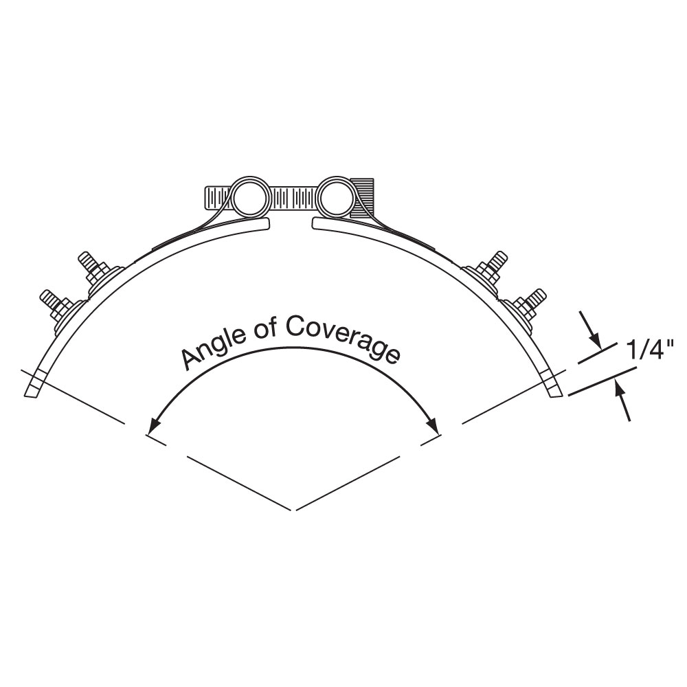
Angle of Coverage Drawing
Partial Coverage Band with Separate Strap (1 Piece)
The alternate method of partial coverage construction is the 1-piece Band Heater with a separate 2-piece strap. The 2-piece strap itself is bolted at the padded ends, allowing the heater to float between the pads as illustrated below. When tightening the strap, it will pull the heater against the cylinder being heated. The standard center of hole to edge of heater dimension is 1/4″.
Clamping Options
No options available for this section based on your selections
Type NB: Standard Built-In Clamping Strap, One-Piece Band
The clamping brackets of the Mi-Plus Heater are formed from its outer sheath, producing a unique Built-In Strap. Clamping power is generated through barrel nuts and 1/4-20 alloy steel socket head cap screws, which are an integral part of the Built-In Strap.
Standard on all Mi-Plus heaters 3″ in diameter & larger
Type NS: Standard Built-In Clamping Strap, Two-Piece Band
The clamping brackets of the Mi-Plus Heater are formed from its outer sheath, producing a unique Built-In Strap. Clamping power is generated through barrel nuts and 1/4-20 alloy steel socket head cap screws, which are an integral part of the Built-In Strap.
Standard on all Mi-Plus heaters 3″ in diameter & larger
Type NE: Standard Built-In Clamping Strap, One-Piece Expandable Band
The clamping brackets of the Mi-Plus Heater are formed from its outer sheath, producing a unique Built-In Strap. Clamping power is generated through barrel nuts and 1/4-20 alloy steel socket head cap screws, which are an integral part of the Built-In Strap.
Standard on all Mi-Plus heaters 3″ in diameter & larger.
This option uses a separate strap to properly clamp the heater. A separate strap is useful when clearance is limited or there is an obstruction. Separate straps are made strictly to customer specifications.
This option uses a separate strap to properly clamp the heater. A separate strap is useful when clearance is limited or there is an obstruction. Separate straps are made strictly to customer specifications.
Bolt Size
Clearance
Suggested Diameter Range
8-32
.50″
1″ – 3″
10-32
.56″
2″ – 6″
1/4-20
.62″
> 3″
Scroll for more
Type SS: Separate Clamping Straps, Two-Piece Band
This option uses a separate strap to properly clamp the heater. A separate strap is useful when clearance is limited or there is an obstruction. Separate straps are made strictly to customer specifications.
This option uses a separate strap to properly clamp the heater. A separate strap is useful when clearance is limited or there is an obstruction. Separate straps are made strictly to customer specifications.
Bolt Size
Clearance
Suggested
Diameter Range
8-32
.50″
1″ – 3″
10-32
.56″
2″ – 6″
1/4-20
.62″
> 3″
Scroll for more
Type SE: Separate Clamping Straps, One-Piece Expandable Band
This option uses a separate strap to properly clamp the heater. A separate strap is useful when clearance is limited or there is an obstruction. Separate straps are made strictly to customer specifications.
Type SE: Separate Clamping Straps, One-Piece Expandable Band
This option uses a separate strap to properly clamp the heater. A separate strap is useful when clearance is limited or there is an obstruction. Separate straps are made strictly to customer specifications.
Bolt Size
Clearance
Suggested Diameter Range
8-32
.50″
1″ – 3″
10-32
.56″
2″ – 6″
1/4-20
.62″
> 3″
Scroll for more
Type LB: Low-Profile Built-In Clamping Strap, One-Piece Band
When space is limited use Tempco’s low profile clamping. This compact design uses 10-32 alloy socket head cap screws. Standard on all Mi-Plus heaters less than 3″ in diameter.
Type LB: Low-Profile Built-In Clamping Strap, One-Piece Band
When space is limited use Tempco’s low profile clamping. This compact design uses 10-32 alloy socket head cap screws. Standard on all Mi-Plus heaters less than 3″ in diameter.
Standard on all Mi-Plus heaters less than 3″ in diameter
Type LS: Low-Profile Built-In Clamping Strap, Two-Piece Band
When space is limited use Tempco’s low profile clamping. This compact design uses 10-32 alloy socket head cap screws. Standard on all Mi-Plus heaters less than 3″ in diameter.
Type LS: Low-Profile Built-In Clamping Strap, Two-Piece Band
When space is limited use Tempco’s low profile clamping. This compact design uses 10-32 alloy socket head cap screws. Standard on all Mi-Plus heaters less than 3″ in diameter.
Standard on all Mi-Plus heaters less than 3″ in diameter
Type LE: Low-Profile Built-In Clamping Strap, One-Piece Expandable Band
When space is limited use Tempco’s low profile clamping. This compact design uses 10-32 alloy socket head cap screws. Standard on all Mi-Plus heaters less than 3″ in diameter.
Type LE: Low-Profile Built-In Clamping Strap, One-Piece Expandable Band
When space is limited use Tempco’s low profile clamping. This compact design uses 10-32 alloy socket head cap screws. Standard on all Mi-Plus heaters less than 3″ in diameter.
Standard on all Mi-Plus heaters less than 3″ in diameter
Type OB: Outrigger Built-In Clamping Strap, One-Piece Band
This design is unique to 1″ wide heaters from 1-3/8″ diameter and greater. Two 8-32 alloy socket head cap screws are used to give 1″ wide heaters the required clamping power.
Type OB: Outrigger Built-In Clamping Strap, One-Piece Band
This design is unique to 1″ wide heaters from 1-3/8″ diameter and greater. Two 8-32 alloy socket head cap screws are used to give 1″ wide heaters the required clamping power.
Standard on Mi-Plus heaters 1″ wide and 1-3/8″ in diameter and greater.
Type OS: Outrigger Built-In Clamping Strap, Two-Piece Band
This design is unique to 1″ wide heaters from 1-3/8″ diameter and greater. Two 8-32 alloy socket head cap screws are used to give 1″ wide heaters the required clamping power.
Type OS: Outrigger Built-In Clamping Strap, Two-Piece Band
This design is unique to 1″ wide heaters from 1-3/8″ diameter and greater. Two 8-32 alloy socket head cap screws are used to give 1″ wide heaters the required clamping power.
Standard on Mi-Plus heaters 1″ wide and 1-3/8″ in diameter and greater.
Type SL: Spring Loaded Built-In Clamping Strap, One-Piece Band
Spring loaded clamping with alloy steel socket head cap screws is standard on heaters over 8″ in diameter and offered as an option on any heater with standard brackets. The extra heavy duty compression springs serve to combat thermal expansion of the heater by self adjustment, thereby ensuring excellent contact of the heater surface with the machine barrel or die. This type of clamping is also useful on heaters that are mounted vertically.
Limitations
Minimum Width: 1-1/2″ (38.1 mm)
Minimum Diameter: 3-1/2″ (88.9 mm)
Type NSL: Spring Loaded Built-In Clamping Strap, Two-Piece Band
Spring loaded clamping with alloy steel socket head cap screws is standard on heaters over 8″ in diameter and offered as an option on any heater with standard brackets. The extra heavy duty compression springs serve to combat thermal expansion of the heater by self adjustment, thereby ensuring excellent contact of the heater surface with the machine barrel or die. This type of clamping is also useful on heaters that are mounted vertically.
Type NEL: Spring Loaded Built-In Clamping Strap, One-Piece Expandable Band
Spring loaded clamping with alloy steel socket head cap screws is standard on heaters over 8″ in diameter and offered as an option on any heater with standard brackets. The extra heavy duty compression springs serve to combat thermal expansion of the heater by self adjustment, thereby ensuring excellent contact of the heater surface with the machine barrel or die. This type of clamping is also useful on heaters that are mounted vertically.
Limitations
Minimum Width: 1-1/2″ (38.1 mm)
Minimum Diameter: 3-1/2″ (88.9 mm)
Type WB: Weld-On Bracket, One-Piece Band
The Mi-Plus is available without built-in brackets. For this option, brackets are welded onto the heater plate at user-specified locations. A weld-on bracket is useful when clearance is limited or there is an obstruction for using separate straps. Consult Tempco with your requirements.
The Mi-Plus is available without built-in brackets. For this option, brackets are welded onto the heater plate at user-specified locations. A weld-on bracket is useful when clearance is limited or there is an obstruction for using separate straps. Consult Tempco with your requirements.
Limitations
Minimum Width: 1″ (25.4 mm)
Minimum Diameter: 1″ (25.4 mm)
Bolt Size
Clearance
8-32
.50″
10-32
.56″
1/4-20
.62″
Scroll for more
Type WS: Weld-On Bracket, Two-Piece Band
The Mi-Plus is available without built-in brackets. For this option, brackets are welded onto the heater plate at user-specified locations. A weld-on bracket is useful when clearance is limited or there is an obstruction for using separate straps. Consult Tempco with your requirements.
The Mi-Plus is available without built-in brackets. For this option, brackets are welded onto the heater plate at user-specified locations. A weld-on bracket is useful when clearance is limited or there is an obstruction for using separate straps. Consult Tempco with your requirements.
Limitations
Minimum Width: 1″ (25.4 mm)
Minimum Diameter: 1″ (25.4 mm)
Bolt Size
Clearance
8-32
.50″
10-32
.56″
1/4-20
.62″
Scroll for more
Type WE: Weld-On Bracket, One-Piece Expandable Band
The Mi-Plus is available without built-in brackets. For this option, brackets are welded onto the heater plate at user-specified locations. A weld-on bracket is useful when clearance is limited or there is an obstruction for using separate straps. Consult Tempco with your requirements.
Standard Termination Location: opposite the gap; center of width
Minimum Inside Diameter: 2-1/2″ (63.5 mm)
Minimum Width: 1-1/2″ (38.1 mm)
Post Terminals: 10-32 or 8-32
Maximum Volts: 480VAC
Maximum Amps: 25A (10-32) or 20A (8-32)
The specially designed Stainless Steel Power Terminals are internally connected to the heater and are resistant to over-torquing. The screw terminals are virtually unbreakable. Secure tightening of the electrical connections is essential for safety and long heater life.
Type T2: Screw Terminals, Two-Piece Band
Standard Termination Location: center each half; center of width
Minimum Inside Diameter: 3″ (76.2 mm)
Minimum Width: 1-1/2″ (38.1 mm)
Post Terminals: 10-32 or 8-32
Maximum Volts/Amps: 480VAC/ 25A (10-32) or 20A (8-32) each half
Standard Termination Location: center each half; center of width
Minimum Inside Diameter: 3″ (76.2 mm)
Minimum Width: 1-1/2″ (38.1 mm)
Post Terminals: 10-32 or 8-32
Maximum Volts/Amps: 480VAC/ 25A (10-32) or 20A (8-32) each half
The specially designed Stainless Steel Power Terminals are internally connected to the heater and are resistant to over-torquing. The screw terminals are virtually unbreakable. Secure tightening of the electrical connections is essential for safety and long heater life.
Type T2: Screw Terminals, One-Piece Expandable Band
Standard Termination Location: center each half; center of width
Minimum Inside Diameter: 2-1/2″ (63.5 mm)
Minimum Width: 1-1/2″ (38.1 mm)
Post Terminals: 10-32 or 8-32
Maximum Volts/Amps: 480VAC/ 25A (10-32) or 20A (8-32) each half
Type T2: Screw Terminals, One-Piece Expandable Band
Standard Termination Location: center each half; center of width
Minimum Inside Diameter: 2-1/2″ (63.5 mm)
Minimum Width: 1-1/2″ (38.1 mm)
Post Terminals: 10-32 or 8-32
Maximum Volts/Amps: 480VAC/ 25A (10-32) or 20A (8-32) each half
The specially designed Stainless Steel Power Terminals are internally connected to the heater and are resistant to over-torquing. The screw terminals are virtually unbreakable. Secure tightening of the electrical connections is essential for safety and long heater life.
Type T3X: Screw Terminals, One-Piece Band
Standard Termination Location: opposite the gap; across center of width
Minimum Inside Diameter: 2-1/2″ (63.5 mm)
Minimum Width: with 10-32 Post Terminals — 2-1/2″ (63.5 mm) with 8-32 Post Terminals — 2″ (50.8 mm)
Maximum Volts/Amps: 480VAC/ 25A (10-32) or 20A (8-32) each half
Standard Termination Location: opposite the gap; across center of width
Minimum Inside Diameter: 2-1/2″ (63.5 mm)
Minimum Width: with 10-32 Post Terminals — 2-1/2″ (63.5 mm) with 8-32 Post Terminals — 2″ (50.8 mm)
Maximum Volts/Amps: 480VAC/ 25A (10-32) or 20A (8-32) each half
The specially designed Stainless Steel Power Terminals are internally connected to the heater and are resistant to over-torquing. The screw terminals are virtually unbreakable. Secure tightening of the electrical connections is essential for safety and long heater life.
Type T3X: Screw Terminals, Two-Piece Band
Standard Termination Location: opposite the gap; across center of width
Minimum Inside Diameter: 3″ (76.2 mm)
Minimum Width: with 10-32 Post Terminals — 2-1/2″ (63.5 mm) with 8-32 Post Terminals — 2″ (50.8 mm)
Maximum Volts/Amps: 480VAC/ 25A (10-32) or 20A (8-32) each half
Standard Termination Location: opposite the gap; across center of width
Minimum Inside Diameter: 3″ (76.2 mm)
Minimum Width: with 10-32 Post Terminals — 2-1/2″ (63.5 mm) with 8-32 Post Terminals — 2″ (50.8 mm)
Maximum Volts/Amps: 480VAC/ 25A (10-32) or 20A (8-32) each half
The specially designed Stainless Steel Power Terminals are internally connected to the heater and are resistant to over-torquing. The screw terminals are virtually unbreakable. Secure tightening of the electrical connections is essential for safety and long heater life.
Type T3X: Screw Terminals, One-Piece Expandable Band
Standard Termination Location: opposite the gap; across center of width
Minimum Inside Diameter: 2-1/2″ (63.5 mm)
Minimum Width: with 10-32 Post Terminals — 2-1/2″ (63.5 mm) with 8-32 Post Terminals — 2″ (50.8 mm)
Maximum Volts/Amps: 480VAC/ 25A (10-32) or 20A (8-32) each half
The specially designed Stainless Steel Power Terminals are internally connected to the heater and are resistant to over-torquing. The screw terminals are virtually unbreakable. Secure tightening of the electrical connections is essential for safety and long heater life.
Type T3Y: Screw Terminals, Two-Piece Band
Standard Termination Location: next to same gap on each half; across center of width
Minimum Inside Diameter: 3″ (76.2 mm)
Minimum Width: with 8-32 Post Terminals — 2″ (50.8 mm) with 10-32 Post Terminals — 2-1/2″ (63.5 mm)
Standard Termination Location: next to same gap on each half; across center of width
Minimum Inside Diameter: 3″ (76.2 mm)
Minimum Width: with 8-32 Post Terminals — 2″ (50.8 mm) with 10-32 Post Terminals — 2-1/2″ (63.5 mm)
Maximum Volts: 480VAC each half
Maximum Amps: 25A (10-32) or 20A (8-32) each hal
The specially designed Stainless Steel Power Terminals are internally connected to the heater and are resistant to over-torquing. The screw terminals are virtually unbreakable. Secure tightening of the electrical connections is essential for safety and long heater life.
Type W1: Abrasion-Resistant Straight Wire Braid Leads, One-Piece Band
Standard Termination Location: opposite the gap; center of width
Type W1: Abrasion-Resistant Straight Wire Braid Leads, One-Piece Band
Standard Termination Location: opposite the gap; center of width
Minimum Inside Diameter: 1″ (25.4 mm)
Minimum Width: 1″ (25.4 mm)
Maximum Volts: 480VAC
Maximum Amps: 12.5
The lead wires exit straight out through a stainless steel eyelet. Flexible stainless steel wire braid leads are highly recommended for improved abrasion resistance. Wire braid leads offer sharp bending not possible with armor cable.
This stainless steel braid is loosely wrapped around two mica insulated lead wires rated for 842°F (450°C). The standard leads are 10″ of stainless steel loose wire braid over 12″ of flexible leads.
Type W1: Abrasion-Resistant Straight Wire Braid Leads, Two-Piece Band
Standard Termination Location: center of each half; center of width
Type W1: Abrasion-Resistant Straight Wire Braid Leads, Two-Piece Band
Standard Termination Location: center of each half; center of width
Minimum Inside Diameter: 3″ (76.2 mm)
Minimum Width: 1″ (25.4 mm)
Maximum Volts: 480VAC each half
Maximum Amps: 12.5A each half
The lead wires exit straight out through a stainless steel eyelet. Flexible stainless steel wire braid leads are highly recommended for improved abrasion resistance. Wire braid leads offer sharp bending not possible with armor cable. This stainless steel braid is loosely wrapped around two mica insulated lead wires rated for 842°F (450°C). The standard leads are 10″ of stainless steel loose wire braid over 12″ of flexible leads.
Type W1: Abrasion-Resistant Straight Wire Braid Leads, One-Piece Expandable Band
Standard Termination Location: two sets of leads opposite the gap; center of width
Type W1: Abrasion-Resistant Straight Wire Braid Leads, One-Piece Expandable Band
Standard Termination Location: two sets of leads opposite the gap; center of width
Minimum Inside Diameter: 2-1/2″ (63.5 mm)
Minimum Width: 1-1/2″ (38.1 mm)
Maximum Volts/Amps: 480VAC/12.5A each half
The lead wires exit straight out through a stainless steel eyelet. Flexible stainless steel wire braid leads are highly recommended for improved abrasion resistance. Wire braid leads offer sharp bending not possible with armor cable. This stainless steel braid is loosely wrapped around two mica insulated lead wires rated for 842°F (450°C). The standard leads are 10″ of stainless steel loose wire braid over 12″ of flexible leads.
Type W2: Right-Angle Wire Braid Leads, 90 Degrees to Heater Diameter, One-Piece Band
Standard Termination Location: opposite the gap; near edge of width
Type W2: Right-Angle Wire Braid Leads, 90 Degrees to Heater Diameter, One-Piece Band
Standard Termination Location: opposite the gap; near edge of width
Minimum Inside Diameter: 1″ (25.4 mm)
Minimum Width: 1″ (25.4 mm)
Maximum Volts: 480VAC
Maximum Amps: 12.5
This style of wiring is the most prevalent for nozzle band heaters, as it contributes to the most flexible and space saving installation.
Mica insulated lead wires rated for 842°F (450°C) with tightly wrapped stainless steel overbraid are used, providing protection in abrasive environments. The stainless steel braid exits parallel to the heater centerline through a low profile stainless steel cap. This cap also acts as a strain relief, guarding against excessive flexing or pulling of the lead wire.
By keeping the lead wires away from the heater, less damage from high temperature contact is likely to occur.
The standard leads are 10″ of stainless steel wire braid over 12″ of flexible leads.
Type W2: Right-Angle Wire Braid Leads, 90 Degrees to Heater Diameter, Two-Piece Band
Standard Termination Location: center of each half; near edge of width
Type W2: Right-Angle Wire Braid Leads, 90 Degrees to Heater Diameter, Two-Piece Band
Standard Termination Location: center of each half; near edge of width
Minimum Inside Diameter: 3″ (76.2 mm)
Minimum Width: 1″ (25.4 mm)
Maximum Volts/Amps: 480VAC/12.5A each half
This style of wiring is the most prevalent for nozzle band heaters, as it contributes to the most flexible and space saving installation.
Mica insulated lead wires rated for 842°F (450°C) with tightly wrapped stainless steel overbraid are used, providing protection in abrasive environments. The stainless steel braid exits parallel to the heater centerline through a low profile stainless steel cap. This cap also acts as a strain relief, guarding against excessive flexing or pulling of the lead wire.
By keeping the lead wires away from the heater, less damage from high temperature contact is likely to occur.
The standard leads are 10″ of stainless steel wire braid over 12″ of flexible leads.
Type W2: Right-Angle Wire Braid Leads, 90 Degrees to Heater Diameter, One-Piece Expandable Band
Standard Termination Location: two sets of leads opposite the gap; center of width
Type W5: Right-Angle Wire Braid Leads, 90 Degrees to Heater Width, One-Piece Band
Standard Termination Location: opposite the gap; center of width
Minimum Inside Diameter: 1″ (25.4 mm)
Minimum Width: 1″ (25.4 mm)
Maximum Volts: 480VAC
Maximum Amps: 10
The stainless steel braid exits parallel to the heater surface through a low profile stainless steel cap, which also acts as a strain relief guarding against excessive flexing or pulling of the lead wire. Mica insulated lead wires rated for 842°F (450°C) with tightly wrapped stainless steel overbraid are used, providing protection in abrasive environments.
This low-profile termination is convenient where space limitations are a concern.
The standard leads are 10″ of stainless steel wire braid over 12″ of
flexible leads.
Type W5: Right-Angle Wire Braid Leads, 90 Degrees to Heater Width, Two-Piece Band
Standard Termination Location: center of each half; center of width
Type W5: Right-Angle Wire Braid Leads, 90 Degrees to Heater Width, Two-Piece Band
Standard Termination Location: center of each half; center of width
Minimum Inside Diameter: 3″ (76.2 mm)
Minimum Width: 1″ (25.4 mm)
Maximum Volts: 480VAC each half
Maximum Amps: 10 each half
The stainless steel braid exits parallel to the heater surface through a low profile stainless steel cap, which also acts as a strain relief guarding against excessive flexing or pulling of the lead wire. Mica insulated lead wires rated for 842°F (450°C) with tightly wrapped stainless steel overbraid are used, providing protection in abrasive environments.
This low-profile termination is convenient where space limitations are a concern.
The standard leads are 10″ of stainless steel wire braid over 12″ of
flexible leads.
Type R1: Abrasion-Resistant Straight Armor Cable, One-Piece Band
Standard Termination Location: opposite the gap; center of width
Type R1: Abrasion-Resistant Straight Armor Cable, One-Piece Band
Standard Termination Location: opposite the gap; center of width
Minimum Inside Diameter: 1″ (25.4 mm)
Minimum Width: 1″ (25.4 mm)
Maximum Volts: 480VAC
Maximum Amps: 12.5
Stainless steel armor cable provides vastly superior lead wire protection in cases where abrasion is a constant problem. The lead wires are mica insulated and rated for 842°F (450°C).
The standard leads are 10″ of stainless steel armor cable over 12″ lead wire.
Type R1: Abrasion-Resistant Straight Armor Cable, Two-Piece Band
Standard Termination Location: center of each half; center of width
Type R1: Abrasion-Resistant Straight Armor Cable, Two-Piece Band
Standard Termination Location: center of each half; center of width
Minimum Inside Diameter: 3″ (76.2 mm)
Minimum Width: 1″ (25.4 mm)
Maximum Volts/Amps: 480VAC/12.5A each half
Stainless steel armor cable provides vastly superior lead wire protection in cases where abrasion is a constant problem. The lead wires are mica insulated and rated for 842°F (450°C).
The standard leads are 10″ of stainless steel armor cable over 12″ lead wire.
Type R1: Abrasion-Resistant Straight Armor Cable, One-Piece Expandable Band
Standard Termination Location: two sets of leads opposite the gap; center of width
Type R1: Abrasion-Resistant Straight Armor Cable, One-Piece Expandable Band
Standard Termination Location: two sets of leads opposite the gap; center of width
Minimum Inside Diameter: 2-1/2″ (63.5 mm)
Minimum Width: 1-1/2″ (38.1 mm)
Maximum Volts/Amps: 480VAC/12.5A each half
Stainless steel armor cable provides vastly superior lead wire protection in cases where abrasion is a constant problem. The lead wires are mica insulated and rated for 842°F (450°C).
The standard leads are 10″ of stainless steel armor cable over 12″ lead wire.
Type R2B: Abrasion-Resistant Right Angle Armor Cable, One-Piece Band
Standard Termination Location: opposite the gap; center of width
Type R2B: Abrasion-Resistant Right Angle Armor Cable, One-Piece Band
Standard Termination Location: opposite the gap; center of width
Minimum Inside Diameter: 1″ (25.4 mm)
Minimum Width: 1″ (25.4 mm)
Maximum Volts/Amps: 480VAC/12.5A
Stainless Steel Right-Angle Armor Cable will provide excellent lead wire protection. This space saving termination will give long-term abrasion protection. The lead wires are mica insulated and rated for 842°F (450°C).
The standard leads are 10″ of stainless steel armor cable over 12″ of lead wire.
Type R2B: Abrasion-Resistant Right Angle Armor Cable, Two-Piece Band
Standard Termination Location: center of each half; center of width
Type R2B: Abrasion-Resistant Right Angle Armor Cable, Two-Piece Band
Standard Termination Location: center of each half; center of width
Minimum Inside Diameter: 3″ (76.2 mm)
Minimum Width: 1″ (25.4 mm)
Maximum Volts/Amps: 480VAC/12.5A each half
Stainless Steel Right-Angle Armor Cable will provide excellent lead wire protection. This space saving termination will give long-term abrasion protection. The lead wires are mica insulated and rated for 842°F (450°C).
The standard leads are 10″ of stainless steel armor cable over 12″ of lead wire.
Type R2B: Abrasion-Resistant Right Angle Armor Cable, One-Piece Expandable Band
Standard Termination Location: two sets of leads opposite the gap; center of width
Type R2B: Abrasion-Resistant Right Angle Armor Cable, One-Piece Expandable Band
Standard Termination Location: two sets of leads opposite the gap; center of width
Minimum Inside Diameter: 2-1/2″ (63.5 mm)
Minimum Width: 1-1/2″ (38.1 mm)
Maximum Volts/Amps: 480VAC/12.5A each half
Stainless Steel Right-Angle Armor Cable will provide excellent lead wire protection. This space saving termination will give long-term abrasion protection. The lead wires are mica insulated and rated for 842°F (450°C).
The standard leads are 10″ of stainless steel armor cable over 12″ of lead wire.
Type R2H: Abrasion-Resistant Right Angle Armor Cable for Type HTL Lead Wire, One-Piece Band
Standard Termination Location: opposite the gap; center of width
Type C: General Purpose Terminal Box, One-Piece Band
Standard Termination Location: opposite the gap; center of width
Minimum Inside Diameter: 3″ (76.2 mm)
Minimum Width: 2″ (50.8 mm)
Maximum Volts/Amps: 480VAC/25A
The Heavy Duty Stainless Steel Terminal Box has a 1/2″ trade size knockout (actual diameter 7/8″) that will accept standard armor cable connectors. To simplify installation, Mi-Plus band heaters with terminal boxes can be pre-wired. Type CA – Box only (shown) Type CD – Box with prewired SS wire braid Type CC – Box with prewired SS armor cable Type CE – Box with prewired plain leads
Type C: General Purpose Terminal Box, Two-Piece Band
Standard Termination Location: center of each half; center of width
Type C: General Purpose Terminal Box, Two-Piece Band
Standard Termination Location: center of each half; center of width
Minimum Inside Diameter: 3″ (76.2 mm)
Minimum Width: 2″ (50.8 mm)
Maximum Volts/Amps: 480VAC/25A each half
The Heavy Duty Stainless Steel Terminal Box has a 1/2″ trade size knockout (actual diameter 7/8″) that will accept standard armor cable connectors. To simplify installation, Mi-Plus band heaters with terminal boxes can be pre-wired. Type CA – Box only (shown) Type CD – Box with prewired SS wire braid Type CC – Box with prewired SS armor cable Type CE – Box with prewired plain leads
Type C: General Purpose Terminal Box, One-Piece Expandable Band
Standard Termination Location: opposite the gap; center of width
Type C: General Purpose Terminal Box, One-Piece Expandable Band
Standard Termination Location: opposite the gap; center of width
Minimum Inside Diameter: 3″ (76.2 mm)
Minimum Width: 2″ (50.8 mm)
Maximum Volts/Amps: 480VAC/25A each half
The Heavy Duty Stainless Steel Terminal Box has a 1/2″ trade size knockout (actual diameter 7/8″) that will accept standard armor cable connectors. To simplify installation, Mi-Plus band heaters with terminal boxes can be pre-wired. Type CA – Box only (shown) Type CD – Box with prewired SS wire braid Type CC – Box with prewired SS armor cable Type CE – Box with prewired plain leads
Type L1: Plain Wire Leads, One-Piece Band
Standard Termination Location: opposite the gap; center of width
Standard Termination Location: opposite the gap; center of width
Minimum Inside Diameter: 1″ (25.4 mm)
Minimum Width: 1″ (25.4 mm)
Maximum Volts/Amps: 480VAC/12.5A
Plain wire leads are available on all construction styles. The lead wires exit straight out through a stainless steel eyelet. High-temperature 842°F (450°C) mica insulated lead wire is standard.
The standard lead length is 10″ long.
Plain wire leads do not offer protection against contamination or abrasion.
Type L1: Plain Wire Leads, Two-Piece Band
Standard Termination Location: center of each half; center of width
Standard Termination Location: center of each half; center of width
Minimum Inside Diameter: 3″ (76.2 mm)
Minimum Width: 1″ (25.4 mm)
Maximum Volts/Amps: 480VAC/12.5A each half
Plain wire leads are available on all construction styles. The lead wires exit straight out through a stainless steel eyelet. High-temperature 842°F (450°C) mica insulated lead wire is standard.
The standard lead length is 10″ long.
Plain wire leads do not offer protection against contamination or abrasion.
Type L1: Plain Wire Leads, One-Piece Expandable Band
Standard Termination Location: two sets of leads opposite the gap; center of width
Type L1: Plain Wire Leads, One-Piece Expandable Band
Standard Termination Location: two sets of leads opposite the gap; center of width
Minimum Inside Diameter: 2-1/2″ (63.5 mm)
Minimum Width: 1-1/2″ (38.1 mm)
Maximum Volts/Amps: 480VAC/12.5A each half
Plain wire leads are available on all construction styles. The lead wires exit straight out through a stainless steel eyelet. High-temperature 842°F (450°C) mica insulated lead wire is standard.
The standard lead length is 10″ long.
Plain wire leads do not offer protection against contamination or abrasion.
Type P1: Quick Disconnect Plugs, One-Piece Band
Standard Termination Location: opposite the gap; center of width
Standard Termination Location: opposite the gap; center of width
Minimum Inside Diameter: 3″ (76.2 mm)
Minimum Width: 2″ (50.8 mm)
Maximum Volts: 250VAC
Maximum Amps: 16
Maximum Temperature: 392°F (200°C)
Quick Disconnect Plugs are a simple, safe and quick way to apply power to a band heater installation. The combination of plug and cup assembly along with stainless steel armor cable or stainless steel wire braid eliminates all live exposed terminals or wiring that can be a potential hazard.
The assembly is available with a straight or right-angle plug. To simplify installation, Mi-Plus band heaters with Quick Disconnects can be pre-wired with stainless steel armor or stainless steel wire braid.
The standard abrasive protection leads are 10″ of protection over 12″ of flexible leads. P1A — Cup Assembly only P1B — Cup Assembly with straight plug P1C — Cup Assembly with 90° plug P1E — Cup Assembly with straight plug and stainless steel armor cable P1F — Cup Assembly with straight plug and stainless steel wire braid P1H — Cup Assembly with 90° plug and stainless steel armor cable P1J — Cup Assembly with 90° plug and stainless steel wire braid
Type P1: Quick Disconnect Plugs, Two-Piece Band
Standard Termination Location: opposite the gap; center of width
Standard Termination Location: opposite the gap; center of width
Minimum Inside Diameter: 3″ (76.2 mm)
Minimum Width: 2″ (50.8 mm)
Maximum Volts: 250VAC
Maximum Amps: 16
Maximum Temperature: 392°F (200°C)
Quick Disconnect Plugs are a simple, safe and quick way to apply power to a band heater installation. The combination of plug and cup assembly along with stainless steel armor cable or stainless steel wire braid eliminates all live exposed terminals or wiring that can be a potential hazard.
The assembly is available with a straight or right-angle plug. To simplify installation, Mi-Plus band heaters with Quick Disconnects can be pre-wired with stainless steel armor or stainless steel wire braid.
The standard abrasive protection leads are 10″ of protection over 12″ of flexible leads. P1A — Cup Assembly only P1B — Cup Assembly with straight plug P1C — Cup Assembly with 90° plug P1E — Cup Assembly with straight plug and stainless steel armor cable P1F — Cup Assembly with straight plug and stainless steel wire braid P1H — Cup Assembly with 90° plug and stainless steel armor cable P1J — Cup Assembly with 90° plug and stainless steel wire braid
Type P2: Terminal Box and High-Temperature Quick Disconnect Straight Plug, One-Piece Band
Standard Termination Location: opposite the gap; center of width
Type P2: Terminal Box and High-Temperature Quick Disconnect Straight Plug, One-Piece Band
Standard Termination Location: opposite the gap; center of width
Minimum Inside Diameter: 3″ (76.2 mm)
Minimum Width: 2″ (50.8 mm)
Maximum Volts: 250VAC
Maximum Amps: 16
Maximum Temperature: 572°F (300°C)
This lower profile terminal box and high temperature quick disconnect plug assembly offers a solution where clearance is a problem. This combination of plug and cup assembly along with stainless steel armor cable or stainless steel wire braid eliminates all live exposed terminals or wiring that can be a potential hazard.
To simplify installation, can be pre-wired with stainless steel armor or stainless steel wire braid. The standard abrasive protection leads are 10″ of protection over 12″ of flexible leads. P2A — Box and Cup only P2B — Box and Cup with straight plug P2D — Box and Cup with straight plug and stainless steel armor cable P2E — Box and Cup with straight plug and stainless steel wire braid
Type P2: Terminal Box and High-Temperature Quick Disconnect Straight Plug, Two-Piece Band
Standard Termination Location: center of each half; center of width
Type P2: Terminal Box and High-Temperature Quick Disconnect Straight Plug, Two-Piece Band
Standard Termination Location: center of each half; center of width
Minimum Inside Diameter: 3″ (76.2 mm)
Minimum Width: 2″ (50.8 mm)
Maximum Volts: 250VAC each half
Maximum Amps: 16 each half
Maximum Temperature: 572°F (300°C)
This lower profile terminal box and high temperature quick disconnect plug assembly offers a solution where clearance is a problem. This combination of plug and cup assembly along with stainless steel armor cable or stainless steel wire braid eliminates all live exposed terminals or wiring that can be a potential hazard.
To simplify installation, can be pre-wired with stainless steel armor or stainless steel wire braid. The standard abrasive protection leads are 10″ of protection over 12″ of flexible leads. P2A — Box and Cup only P2B — Box and Cup with straight plug P2D — Box and Cup with straight plug and stainless steel armor cable P2E — Box and Cup with straight plug and stainless steel wire braid
Type P2: Terminal Box and High-Temperature Quick Disconnect Straight Plug, One-Piece Expandable Band
Standard Termination Location: opposite the gap; center of width
Type P2: Terminal Box and High-Temperature Quick Disconnect Straight Plug, One-Piece Expandable Band
Standard Termination Location: opposite the gap; center of width
Minimum Inside Diameter: 3″ (76.2 mm)
Minimum Width: 2″ (50.8 mm)
Maximum Volts: 250VAC each half
Maximum Amps: 16 each half
Maximum Temperature: 572°F (300°C)
This lower profile terminal box and high temperature quick disconnect plug assembly offers a solution where clearance is a problem. This combination of plug and cup assembly along with stainless steel armor cable or stainless steel wire braid eliminates all live exposed terminals or wiring that can be a potential hazard.
To simplify installation, can be pre-wired with stainless steel armor or stainless steel wire braid. The standard abrasive protection leads are 10″ of protection over 12″ of flexible leads. P2A — Box and Cup only P2B — Box and Cup with straight plug P2D — Box and Cup with straight plug and stainless steel armor cable P2E — Box and Cup with straight plug and stainless steel wire braid
Additional Options
No options available for this section based on your selections
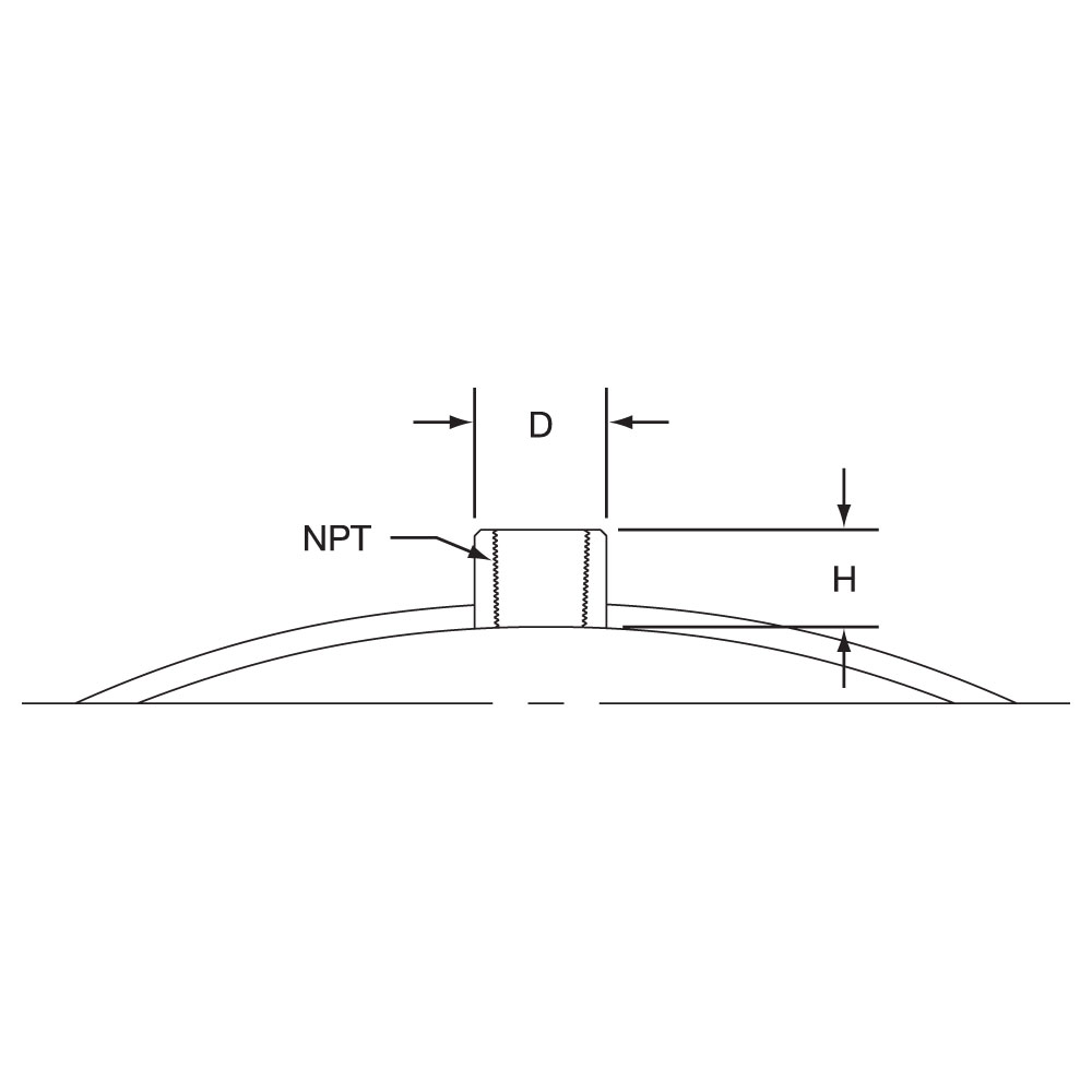
Thermocouple Coupling
The Thermocouple Coupling facilitates the installation of an external thermocouple with a threaded fitting. The standard location for the coupling is 90° from the gap at the center of the width. Specify without through hole for heater sensing or with through hole for load sensing.
The Thermocouple Coupling facilitates the installation of an external thermocouple with a threaded fitting. The standard location for the coupling is 90° from the gap at the center of the width. Specify without through hole for heater sensing or with through hole for load sensing.
Thread
D
H
1/8-27 NPT
9/16″
5/8″
1/4-20 NPT
3/4″
11/16″
3/8-18 NPT
7/8″
5/8″
M12-1.75mm
3/4″
1/2″
Scroll for more
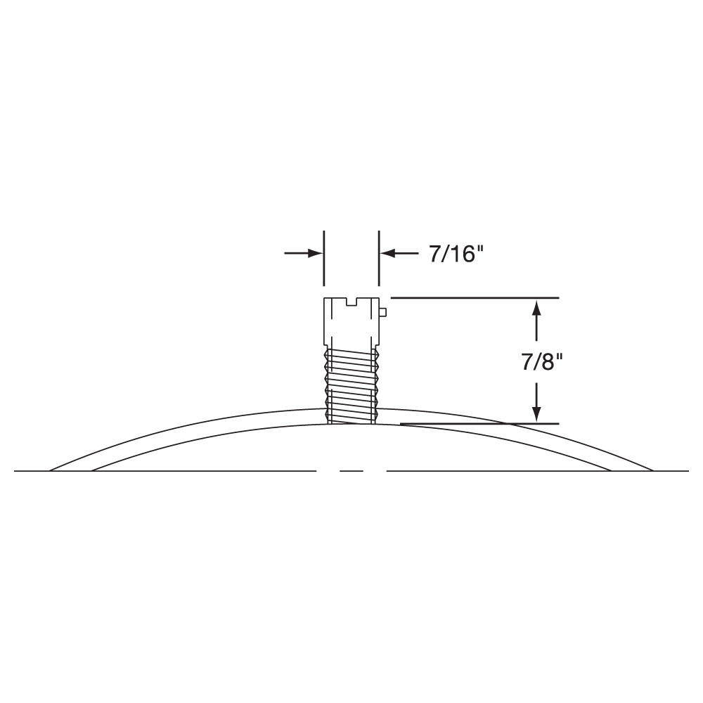
Thermocouple Bayonet Adapter
A standard Bayonet Adapter facilitates the installation of an external thermocouple with a standard bayonet cap. The standard location for the adapter is 90° from the gap. See Temperature Sensors for a complete selection of thermocouples available from stock.
A standard Bayonet Adapter facilitates the installation of an external thermocouple with a standard bayonet cap. The standard location for the adapter is 90° from the gap. See Temperature Sensors for a complete selection of thermocouples available from stock.
Thermocouple Bayonet Adapter
Built-In Thermocouple
A built-in thermocouple can be factory installed on Mi-Plus band heaters. ANSI type J or K thermocouples are available on Type L1, R,1 R2, W1, W2 and W5 lead wire terminations. Thermocouple junction is located inside the exit termination stamping, providing a relative heater temperature. Thermocouple can be located in various positions on the heater. Consult Tempco with your requirements.
A built-in thermocouple can be factory installed on Mi-Plus band heaters. ANSI type J or K thermocouples are available on Type L1, R,1 R2, W1, W2 and W5 lead wire terminations. Thermocouple junction is located inside the exit termination stamping, providing a relative heater temperature. Thermocouple can be located in various positions on the heater. Consult Tempco with your requirements.
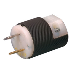
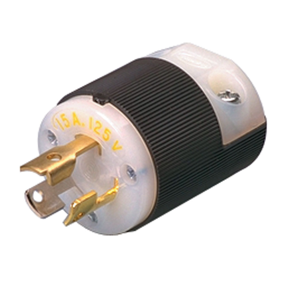
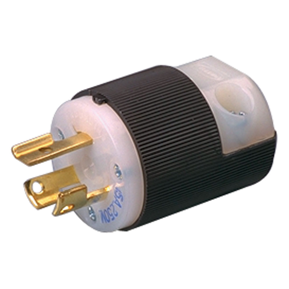
Stock Heavy-Duty Quick Disconnect Plugs and Adapters
Heaters with pre-wired plugs allow quick and easy installation of the heater. These plugs can be attached to armor cable or stainless steel wire braid. For other types of plugs, consult Tempco or specify the manufacturer’s part number when ordering. See Accessories for additional Twist-Lock electrical plugs.
P4 Electrical PlugP5 Electrical Plug
Reference
NEMAP or R
Amps
Volts
Plug Part No.
Connectors (Female) Part No.
P1 twist lock
L1-15
15A
125V
EHD-102-102
EHD-103-101
P2 twist lock
n/a
10A
250V
EHD-102-107
EHD-103-103
15A
125V
P3 straight
5-15
15A
125V
EHD-102-103
EHD-103-102
P4 twist lock
L5-15
15A
125V
EHD-102-113
EHD-103-104
P5 twist lock
L6-15
15A
250V
EHD-102-121
EHD-103-107
P6 twist lock
L6-20
20A
250V
EHD-102-122
EHD-103-150
Scroll for more
Igloo Ceramic Terminal Covers for Screw Terminals
Igloo™ ceramic terminal covers consist of two individual ceramic parts. With a tight-fitting cap and a solid base, an Igloo will fully insulate any standard #8 or #10 terminal lug used for electrical wiring hookups. Igloos can be assembled onto any standard Mi-Plus Band with 8-32 or 10-32 screw terminals.
Igloo™ ceramic terminal covers consist of two individual ceramic parts. With a tight-fitting cap and a solid base, an Igloo will fully insulate any standard #8 or #10 terminal lug used for electrical wiring hookups. Igloos can be assembled onto any standard Mi-Plus Band with 8-32 or 10-32 screw terminals.
Three types of Igloo™ bases are available: Type C6 — Double Port In-Line P/N CER-101-104 Type C7 — Double Port 90° P/N CER-101-106 Type C8 — Single Port P/N CER-101-107
Igloo™ caps are available in the three screw terminal sizes: 10-32 — P/N CER-102-101 10-24 — P/N CER-102-104 8-32 — P/N CER-102-105
When ordering, specify the type of Igloo and the screw terminal size.
Igloo Double Port 90° are recommended on expandable heaters with Type T3X Termination. Igloo Double Port In-Line will not fit on expandable heaters with Type T3X termination.
Type WS: Weld-On Bracket, Two-Piece Band The Mi-Plus is available without built-in brackets. For this option, brackets are welded onto the heater plate at user-specified locations. A weld-on bracket is useful when clearance is limited or there is an obstruction for using separate straps. Consult Tempco with your requirements. Limitations Minimum Width: 1″ (25.4 mm) Minimum Diameter: 1″ (25.4 mm) Clamping Options 2 Piece Additional Options Armor Cable Construction Styles Electrical Terminations Lead Wire Plugs and Connectors Quick Disconnect Plugs Screw Terminals Terminal Covers Terminal Housings Thermocouples Weld-On Brackets Wire Braids Type WE: Weld-On Bracket, One-Piece Expandable Band Limitations Minimum Width: 1″ (25.4 mm) Minimum Diameter: 1″ (25.4 mm) 1 Piece Expandable Type WB: Weld-On Bracket, One-Piece Band 1 Piece Type W5: Right-Angle Wire Braid Leads, 90 Degrees to Heater Width, Two-Piece Band Standard Termination Location: center of each half; center of width Minimum Inside Diameter: 3″ (76.2 mm) Minimum Width: 1″ (25.4 mm) Maximum Volts: 480VAC each half Maximum Amps: 10 each half The stainless steel braid exits parallel to the heater surface through a low profile stainless steel cap, which also acts as a strain relief guarding against excessive flexing or pulling of the lead wire. Mica insulated lead wires rated for 842°F (450°C) with tightly wrapped stainless steel overbraid are used, providing protection in abrasive environments. This low-profile termination is convenient where space limitations are a concern. The standard leads are 10″ of stainless steel wire braid over 12″ of flexible leads. Built-In Clamping Straps Separate Clamping Straps Type W5: Right-Angle Wire Braid Leads, 90 Degrees to Heater Width, One-Piece Band Standard Termination Location: opposite the gap; center of width Minimum Inside Diameter: 1″ (25.4 mm) Minimum Width: 1″ (25.4 mm) Maximum Volts: 480VAC Maximum Amps: 10 Type W2: Right-Angle Wire Braid Leads, 90 Degrees to Heater Diameter, Two-Piece Band Standard Termination Location: center of each half; near edge of width Minimum Inside Diameter: 3″ (76.2 mm) Minimum Width: 1″ (25.4 mm) Maximum Volts/Amps: 480VAC/12.5A each half This style of wiring is the most prevalent for nozzle band heaters, as it contributes to the most flexible and space saving installation. Mica insulated lead wires rated for 842°F (450°C) with tightly wrapped stainless steel overbraid are used, providing protection in abrasive environments. The stainless steel braid exits parallel to the heater centerline through a low profile stainless steel cap. This cap also acts as a strain relief, guarding against excessive flexing or pulling of the lead wire. By keeping the lead wires away from the heater, less damage from high temperature contact is likely to occur. The standard leads are 10″ of stainless steel wire braid over 12″ of flexible leads. Type W2: Right-Angle Wire Braid Leads, 90 Degrees to Heater Diameter, One-Piece Expandable Band Standard Termination Location: two sets of leads opposite the gap; center of width Minimum Inside Diameter: 3″ (76.2 mm) Minimum Width: 1″ (25.4 mm) Maximum Volts/Amps: 480VAC/12.5A each half Type W2: Right-Angle Wire Braid Leads, 90 Degrees to Heater Diameter, One-Piece Band Standard Termination Location: opposite the gap; near edge of width Minimum Inside Diameter: 1″ (25.4 mm) Minimum Width: 1″ (25.4 mm) Maximum Volts: 480VAC Maximum Amps: 12.5 Type W1: Abrasion-Resistant Straight Wire Braid Leads, Two-Piece Band Standard Termination Location: center of each half; center of width Minimum Inside Diameter: 3″ (76.2 mm) Minimum Width: 1″ (25.4 mm) Maximum Volts: 480VAC each half Maximum Amps: 12.5A each half The lead wires exit straight out through a stainless steel eyelet. Flexible stainless steel wire braid leads are highly recommended for improved abrasion resistance. Wire braid leads offer sharp bending not possible with armor cable. This stainless steel braid is loosely wrapped around two mica insulated lead wires rated for 842°F (450°C). The standard leads are 10″ of stainless steel loose wire braid over 12″ of flexible leads. Type W1: Abrasion-Resistant Straight Wire Braid Leads, One-Piece Expandable Band Standard Termination Location: two sets of leads opposite the gap; center of width Minimum Inside Diameter: 2-1/2″ (63.5 mm) Minimum Width: 1-1/2″ (38.1 mm) Maximum Volts/Amps: 480VAC/12.5A each half Type W1: Abrasion-Resistant Straight Wire Braid Leads, One-Piece Band Standard Termination Location: opposite the gap; center of width Minimum Inside Diameter: 1″ (25.4 mm) Minimum Width: 1″ (25.4 mm) Maximum Volts: 480VAC Maximum Amps: 12.5 The lead wires exit straight out through a stainless steel eyelet. Flexible stainless steel wire braid leads are highly recommended for improved abrasion resistance. Wire braid leads offer sharp bending not possible with armor cable. This stainless steel braid is loosely wrapped around two mica insulated lead wires rated for 842°F (450°C). The standard leads are 10″ of stainless steel loose wire braid over 12″ of flexible leads. Type T3X: Screw Terminals, One-Piece Band Standard Termination Location: opposite the gap; across center of width Minimum Inside Diameter: 2-1/2″ (63.5 mm) Minimum Width: with 10-32 Post Terminals — 2-1/2″ (63.5 mm) with 8-32 Post Terminals — 2″ (50.8 mm) Maximum Volts/Amps: 480VAC/ 25A (10-32) or 20A (8-32) each half The specially designed Stainless Steel Power Terminals are internally connected to the heater and are resistant to over-torquing. The screw terminals are virtually unbreakable. Secure tightening of the electrical connections is essential for safety and long heater life. Type T3X: Screw Terminals, One-Piece Expandable Band Type T3Y: Screw Terminals, Two-Piece Band Standard Termination Location: next to same gap on each half; across center of width Minimum Inside Diameter: 3″ (76.2 mm) Minimum Width: with 8-32 Post Terminals — 2″ (50.8 mm) with 10-32 Post Terminals — 2-1/2″ (63.5 mm) Maximum Volts: 480VAC each half Maximum Amps: 25A (10-32) or 20A (8-32) each hal Type T3X: Screw Terminals, Two-Piece Band Standard Termination Location: opposite the gap; across center of width Minimum Inside Diameter: 3″ (76.2 mm) Minimum Width: with 10-32 Post Terminals — 2-1/2″ (63.5 mm) with 8-32 Post Terminals — 2″ (50.8 mm) Maximum Volts/Amps: 480VAC/ 25A (10-32) or 20A (8-32) each half Type T2: Screw Terminals, Two-Piece Band Standard Termination Location: center each half; center of width Minimum Inside Diameter: 3″ (76.2 mm) Minimum Width: 1-1/2″ (38.1 mm) Post Terminals: 10-32 or 8-32 Maximum Volts/Amps: 480VAC/ 25A (10-32) or 20A (8-32) each half Type T2: Screw Terminals, One-Piece Expandable Band Standard Termination Location: center each half; center of width Minimum Inside Diameter: 2-1/2″ (63.5 mm) Minimum Width: 1-1/2″ (38.1 mm) Post Terminals: 10-32 or 8-32 Maximum Volts/Amps: 480VAC/ 25A (10-32) or 20A (8-32) each half Type T2: Screw Terminals, One-Piece Band Standard Termination Location: opposite the gap; center of width Minimum Inside Diameter: 2-1/2″ (63.5 mm) Minimum Width: 1-1/2″ (38.1 mm) Post Terminals: 10-32 or 8-32 Maximum Volts: 480VAC Maximum Amps: 25A (10-32) or 20A (8-32) Type SS: Separate Clamping Straps, Two-Piece Band This option uses a separate strap to properly clamp the heater. A separate strap is useful when clearance is limited or there is an obstruction. Separate straps are made strictly to customer specifications. Type SL: Spring Loaded Built-In Clamping Strap, One-Piece Band Spring loaded clamping with alloy steel socket head cap screws is standard on heaters over 8″ in diameter and offered as an option on any heater with standard brackets. The extra heavy duty compression springs serve to combat thermal expansion of the heater by self adjustment, thereby ensuring excellent contact of the heater surface with the machine barrel or die. This type of clamping is also useful on heaters that are mounted vertically. Limitations Minimum Width: 1-1/2″ (38.1 mm) Minimum Diameter: 3-1/2″ (88.9 mm) Type SB: Separate Clamping Straps, One-Piece Band Type SE: Separate Clamping Straps, One-Piece Expandable Band Type R2H: Abrasion-Resistant Right Angle Armor Cable for Type HTL Lead Wire, Two-Piece Band Standard Termination Location: center of each half; center of width Minimum Inside Diameter: 3″ (76.2 mm) Minimum Width: 1″ (25.4 mm) Maximum Volts/Amps: 480VAC/12.5A each half High Temperature Termination: 1022°F (550°C) Special SS Right-Angle Fitting 3-Conductor Wire Type R2H: Abrasion-Resistant Right Angle Armor Cable for Type HTL Lead Wire, One-Piece Expandable Band Type R2H: Abrasion-Resistant Right Angle Armor Cable for Type HTL Lead Wire, One-Piece Band Standard Termination Location: opposite the gap; center of width Minimum Inside Diameter: 1-1/2″ (38.1 mm) Minimum Width: 1″ (25.4 mm) Maximum Volts/Amps: 480VAC/12.5A Type R2B: Abrasion-Resistant Right Angle Armor Cable, Two-Piece Band Stainless Steel Right-Angle Armor Cable will provide excellent lead wire protection. This space saving termination will give long-term abrasion protection. The lead wires are mica insulated and rated for 842°F (450°C). The standard leads are 10″ of stainless steel armor cable over 12″ of lead wire. Type R2B: Abrasion-Resistant Right Angle Armor Cable, One-Piece Expandable Band Type R2B: Abrasion-Resistant Right Angle Armor Cable, One-Piece Band Standard Termination Location: opposite the gap; center of width Minimum Inside Diameter: 1″ (25.4 mm) Minimum Width: 1″ (25.4 mm) Maximum Volts/Amps: 480VAC/12.5A Type R1: Abrasion-Resistant Straight Armor Cable, One-Piece Band Stainless steel armor cable provides vastly superior lead wire protection in cases where abrasion is a constant problem. The lead wires are mica insulated and rated for 842°F (450°C). The standard leads are 10″ of stainless steel armor cable over 12″ lead wire. Type R1: Abrasion-Resistant Straight Armor Cable, Two-Piece Band Type R1: Abrasion-Resistant Straight Armor Cable, One-Piece Expandable Band Type P2: Terminal Box and High-Temperature Quick Disconnect Straight Plug, Two-Piece Band Standard Termination Location: center of each half; center of width Minimum Inside Diameter: 3″ (76.2 mm) Minimum Width: 2″ (50.8 mm) Maximum Volts: 250VAC each half Maximum Amps: 16 each half Maximum Temperature: 572°F (300°C) This lower profile terminal box and high temperature quick disconnect plug assembly offers a solution where clearance is a problem. This combination of plug and cup assembly along with stainless steel armor cable or stainless steel wire braid eliminates all live exposed terminals or wiring that can be a potential hazard. To simplify installation, can be pre-wired with stainless steel armor or stainless steel wire braid. The standard abrasive protection leads are 10″ of protection over 12″ of flexible leads. P2A — Box and Cup only P2B — Box and Cup with straight plug P2D — Box and Cup with straight plug and stainless steel armor cable P2E — Box and Cup with straight plug and stainless steel wire braid Type P2: Terminal Box and High-Temperature Quick Disconnect Straight Plug, One-Piece Expandable Band Standard Termination Location: opposite the gap; center of width Minimum Inside Diameter: 3″ (76.2 mm) Minimum Width: 2″ (50.8 mm) Maximum Volts: 250VAC each half Maximum Amps: 16 each half Maximum Temperature: 572°F (300°C) Type P2: Terminal Box and High-Temperature Quick Disconnect Straight Plug, One-Piece Band Standard Termination Location: opposite the gap; center of width Minimum Inside Diameter: 3″ (76.2 mm) Minimum Width: 2″ (50.8 mm) Maximum Volts: 250VAC Maximum Amps: 16 Maximum Temperature: 572°F (300°C) Type P1: Quick Disconnect Plugs, Two-Piece Band Standard Termination Location: opposite the gap; center of width Minimum Inside Diameter: 3″ (76.2 mm) Minimum Width: 2″ (50.8 mm) Maximum Volts: 250VAC Maximum Amps: 16 Maximum Temperature: 392°F (200°C) Quick Disconnect Plugs are a simple, safe and quick way to apply power to a band heater installation. The combination of plug and cup assembly along with stainless steel armor cable or stainless steel wire braid eliminates all live exposed terminals or wiring that can be a potential hazard. The assembly is available with a straight or right-angle plug. To simplify installation, Mi-Plus band heaters with Quick Disconnects can be pre-wired with stainless steel armor or stainless steel wire braid. The standard abrasive protection leads are 10″ of protection over 12″ of flexible leads. P1A — Cup Assembly only P1B — Cup Assembly with straight plug P1C — Cup Assembly with 90° plug P1E — Cup Assembly with straight plug and stainless steel armor cable P1F — Cup Assembly with straight plug and stainless steel wire braid P1H — Cup Assembly with 90° plug and stainless steel armor cable P1J — Cup Assembly with 90° plug and stainless steel wire braid Type P1: Quick Disconnect Plugs, One-Piece Band Type OS: Outrigger Built-In Clamping Strap, Two-Piece Band This design is unique to 1″ wide heaters from 1-3/8″ diameter and greater. Two 8-32 alloy socket head cap screws are used to give 1″ wide heaters the required clamping power. Standard on Mi-Plus heaters 1″ wide and 1-3/8″ in diameter and greater. Type OB: Outrigger Built-In Clamping Strap, One-Piece Band Type NSL: Spring Loaded Built-In Clamping Strap, Two-Piece Band Limitations Minimum Width: 1-1/2″ (38.1 mm) Minimum Diameter: 3-1/2″ (88.9 mm) Type NS: Standard Built-In Clamping Strap, Two-Piece Band The clamping brackets of the Mi-Plus Heater are formed from its outer sheath, producing a unique Built-In Strap. Clamping power is generated through barrel nuts and 1/4-20 alloy steel socket head cap screws, which are an integral part of the Built-In Strap. Standard on all Mi-Plus heaters 3″ in diameter & larger Limitations Minimum Width: 1-1/2″ (38.1 mm) Minimum Diameter: 3″ (76.2 mm) Type NEL: Spring Loaded Built-In Clamping Strap, One-Piece Expandable Band Type NE: Standard Built-In Clamping Strap, One-Piece Expandable Band Standard on all Mi-Plus heaters 3″ in diameter & larger. Limitations Minimum Width: 1-1/2″ (38.1 mm) Minimum Diameter: 3″ (76.2 mm) Type NB: Standard Built-In Clamping Strap, One-Piece Band Type LS: Low-Profile Built-In Clamping Strap, Two-Piece Band When space is limited use Tempco’s low profile clamping. This compact design uses 10-32 alloy socket head cap screws. Standard on all Mi-Plus heaters less than 3″ in diameter. Standard on all Mi-Plus heaters less than 3″ in diameter Limitations Minimum Width: 1-1/2″ (38.1 mm) Minimum Diameter: 1-3/8″ (34.9 mm) Type LE: Low-Profile Built-In Clamping Strap, One-Piece Expandable Band Type LB: Low-Profile Built-In Clamping Strap, One-Piece Band Type L1: Plain Wire Leads, One-Piece Expandable Band Plain wire leads are available on all construction styles. The lead wires exit straight out through a stainless steel eyelet. High-temperature 842°F (450°C) mica insulated lead wire is standard. The standard lead length is 10″ long. Plain wire leads do not offer protection against contamination or abrasion. Type L1: Plain Wire Leads, Two-Piece Band Type L1: Plain Wire Leads, One-Piece Band Type C: General Purpose Terminal Box, Two-Piece Band Standard Termination Location: center of each half; center of width Minimum Inside Diameter: 3″ (76.2 mm) Minimum Width: 2″ (50.8 mm) Maximum Volts/Amps: 480VAC/25A each half The Heavy Duty Stainless Steel Terminal Box has a 1/2″ trade size knockout (actual diameter 7/8″) that will accept standard armor cable connectors. To simplify installation, Mi-Plus band heaters with terminal boxes can be pre-wired. Type CA – Box only (shown) Type CD – Box with prewired SS wire braid Type CC – Box with prewired SS armor cable Type CE – Box with prewired plain leads Type C: General Purpose Terminal Box, One-Piece Expandable Band Standard Termination Location: opposite the gap; center of width Minimum Inside Diameter: 3″ (76.2 mm) Minimum Width: 2″ (50.8 mm) Maximum Volts/Amps: 480VAC/25A each half Type C: General Purpose Terminal Box, One-Piece Band Standard Termination Location: opposite the gap; center of width Minimum Inside Diameter: 3″ (76.2 mm) Minimum Width: 2″ (50.8 mm) Maximum Volts/Amps: 480VAC/25A Two-Piece Band Construction Two-piece construction satisfies the need for a heater that can be placed anywhere along the machine barrel and is recommended for larger diameter heaters. The two-piece construction style also provides dual voltage capability as heater halves may be wired together either in series or parallel. Two-piece heaters are rated at full voltage and 1/2 the total wattage for each half. Thermocouple Coupling The Thermocouple Coupling facilitates the installation of an external thermocouple with a threaded fitting. The standard location for the coupling is 90° from the gap at the center of the width. Specify without through hole for heater sensing or with through hole for load sensing. Thermocouple Bayonet Adapter A standard Bayonet Adapter facilitates the installation of an external thermocouple with a standard bayonet cap. The standard location for the adapter is 90° from the gap. See Temperature Sensors for a complete selection of thermocouples available from stock. Stock Heavy-Duty Quick Disconnect Plugs and Adapters Heaters with pre-wired plugs allow quick and easy installation of the heater. These plugs can be attached to armor cable or stainless steel wire braid. For other types of plugs, consult Tempco or specify the manufacturer’s part number when ordering. See Accessories for additional Twist-Lock electrical plugs. Partial Coverage Band with Separate Strap (1 Piece) The alternate method of partial coverage construction is the 1-piece Band Heater with a separate 2-piece strap. The 2-piece strap itself is bolted at the padded ends, allowing the heater to float between the pads as illustrated below. When tightening the strap, it will pull the heater against the cylinder being heated. The standard center of hole to edge of heater dimension is 1/4″. Partial Coverage Band with Built-In Brackets (2 Piece) Partial coverage band heaters are required when an obstruction on the barrel would interfere with a full coverage band. The preferred method of construction is the 2-piece Band Heater with Built-In Brackets. The heater is bolted down to the cylinder at the ends and the built-in low thermal expansion strap pulls the heater tightly against the cylinder being heated. The standard center of hole to edge of heater dimension is 1/4″. One-Piece Expandable Band Construction The expandable construction style allows the heater to be opened up and placed anywhere along the machine barrel, as well as minimizes the unheated area as compared to a two-piece heater. With two heater circuits in a common case this heater naturally lends itself to a dual voltage system. Expandable heaters are rated for each circuit at full voltage and one half of the total wattage. One-Piece Band Construction One-piece heaters provide the most heated surface area but can only be used where the entire heater can be slipped over the end of the barrel. One-piece heaters have built-in, full-width clamping bars. Igloo Ceramic Terminal Covers for Screw Terminals Igloo™ ceramic terminal covers consist of two individual ceramic parts. With a tight-fitting cap and a solid base, an Igloo will fully insulate any standard #8 or #10 terminal lug used for electrical wiring hookups. Igloos can be assembled onto any standard Mi-Plus Band with 8-32 or 10-32 screw terminals. Minimum Inside Diameter: 2-1/2″ (63.5 mm) Minimum Width: 2-1/2″ (63.5 mm) Three types of Igloo™ bases are available: Type C6 — Double Port In-Line P/N CER-101-104 Type C7 — Double Port 90° P/N CER-101-106 Type C8 — Single Port P/N CER-101-107 Igloo™ caps are available in the three screw terminal sizes: 10-32 — P/N CER-102-101 10-24 — P/N CER-102-104 8-32 — P/N CER-102-105 When ordering, specify the type of Igloo and the screw terminal size. Igloo Double Port 90° are recommended on expandable heaters with Type T3X Termination. Igloo Double Port In-Line will not fit on expandable heaters with Type T3X termination. Built-In Thermocouple A built-in thermocouple can be factory installed on Mi-Plus band heaters. ANSI type J or K thermocouples are available on Type L1, R,1 R2, W1, W2 and W5 lead wire terminations. Thermocouple junction is located inside the exit termination stamping, providing a relative heater temperature. Thermocouple can be located in various positions on the heater. Consult Tempco with your requirements.