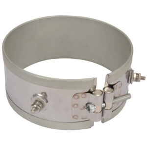
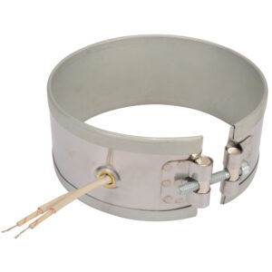
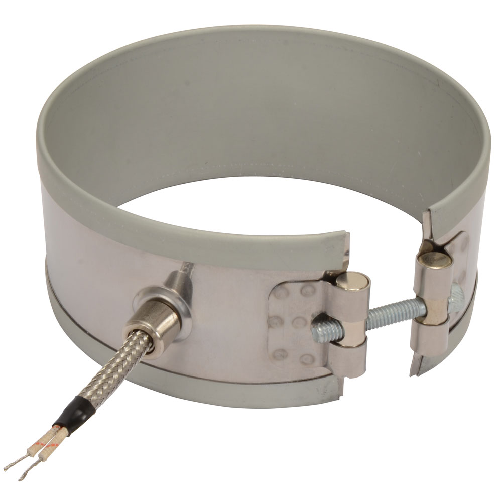
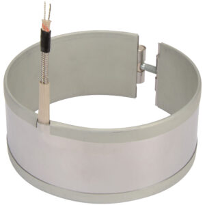
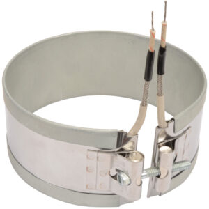
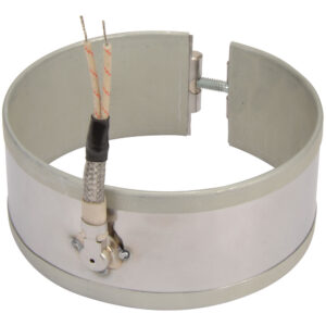
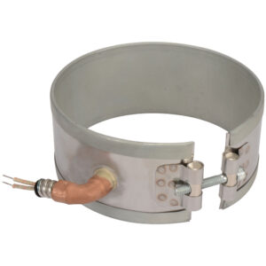
Duraband is a mica insulated heater incorporating a Low Thermal Expansion Alloy outer sheath that is used as a uniquely designed Built-In Strap. It is a proven heater design for good life efficiency and dependability. It assures maintaining the lowest winding temperatures possible, keeping a low-mass heating element assembly for fast heat-up and quick thermal response to controls. It incorporates the Low Thermal Expansion Built-In Strap, a unique design feature originally developed and patented by Tempco.
No options available for this section based on your selections
One-Piece Band Construction
The one-piece construction is available on any screw or lead termination and clamping variation. It can be used where band heaters can be slipped over the end of the cylinder.
The one-piece construction is available on any screw or lead termination and clamping variation. It can be used where band heaters can be slipped over the end of the cylinder.
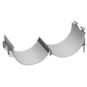
Two-Piece Band Construction
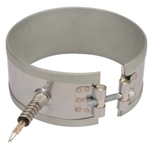
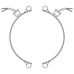
The Duraband two-piece construction provides a built-in hinge, making handling and installation easier. It is used on large cylinders or where the heater cannot be slipped over the end of the cylinder. Two-piece band heaters are rated at watts and volts per each half when ordering.
The Duraband two-piece construction provides a built-in hinge, making handling and installation easier. It is used on large cylinders or where the heater cannot be slipped over the end of the cylinder. Two-piece band heaters are rated at watts and volts per each half when ordering.
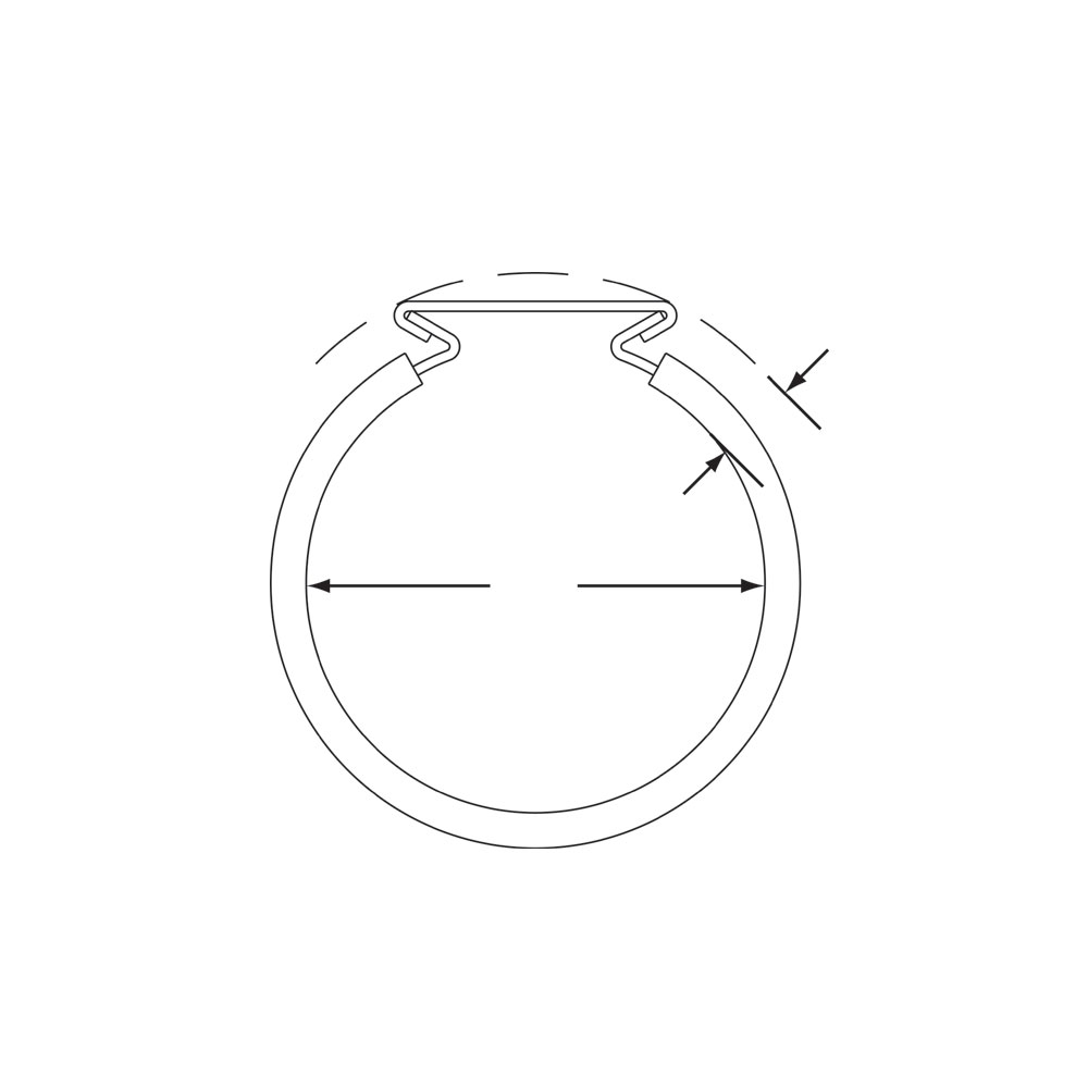
One-Piece Expandable Band Construction
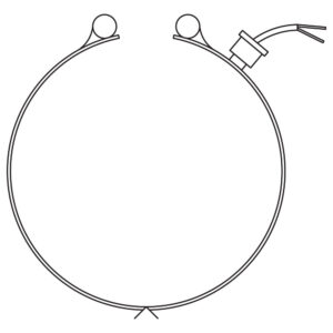
The one-piece expandable construction is available on any screw or lead and clamping variation and can be used where a one-piece band heater would have to be expanded to fit over the barrel during installation, rather than slipped over the end of the barrel.
The one-piece expandable construction is available on any screw or lead and clamping variation and can be used where a one-piece band heater would have to be expanded to fit over the barrel during installation, rather than slipped over the end of the barrel.
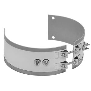
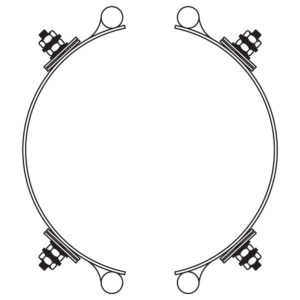
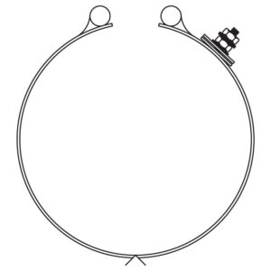
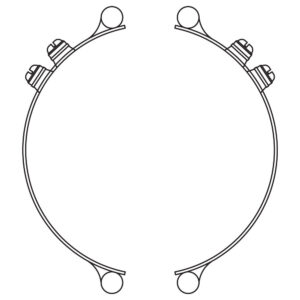
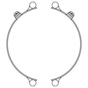
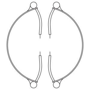
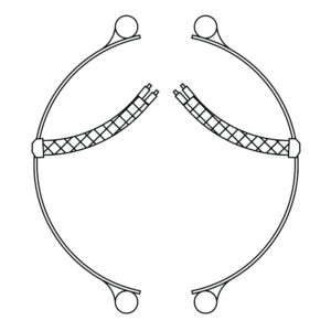
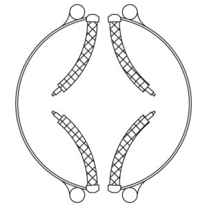
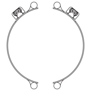
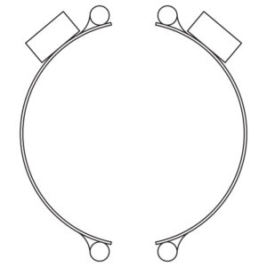
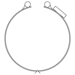
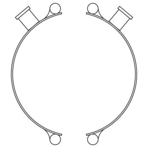
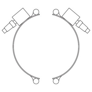
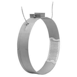
Type NS: Partial Coverage Band with Built-In Brackets (2 Piece)
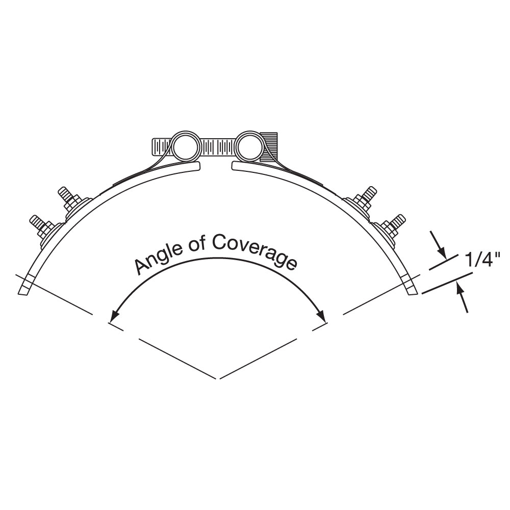
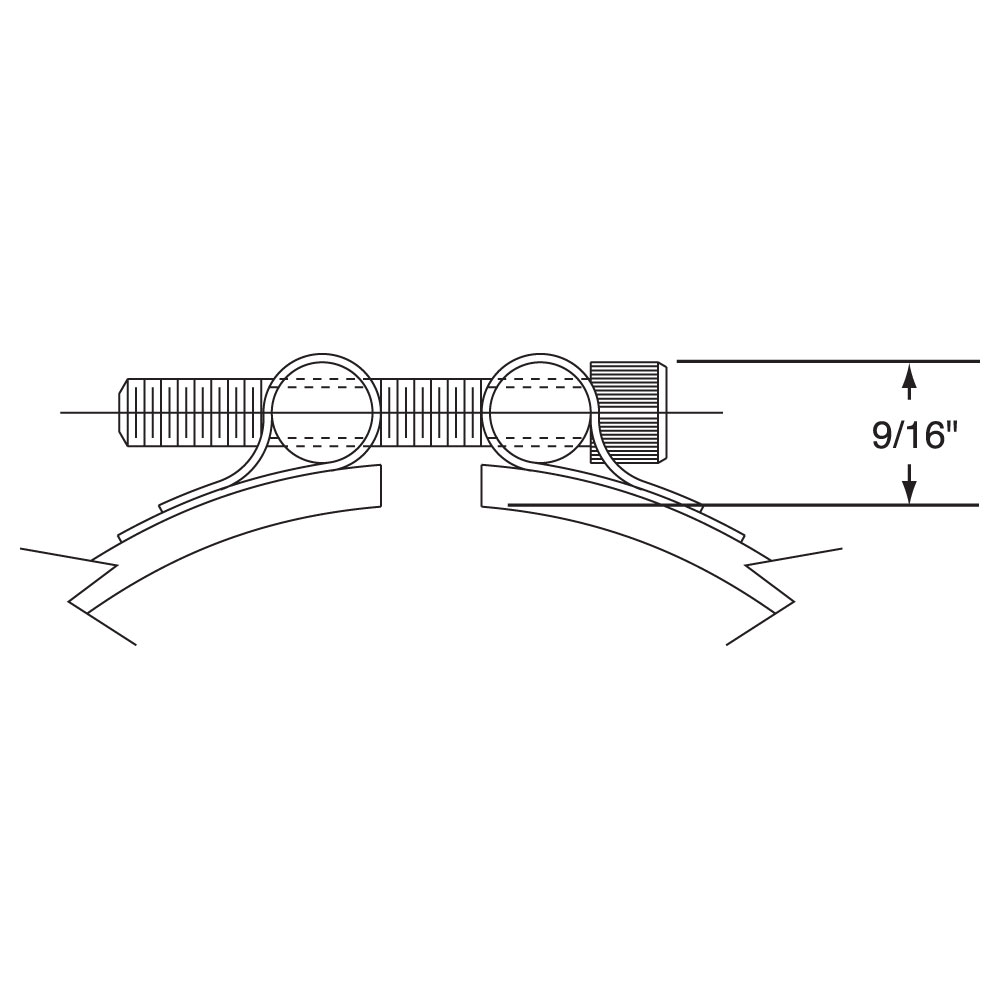
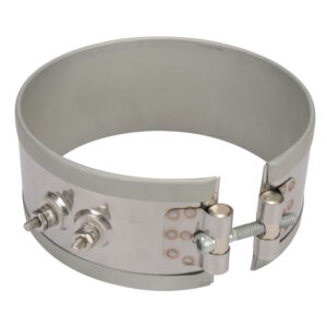
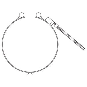
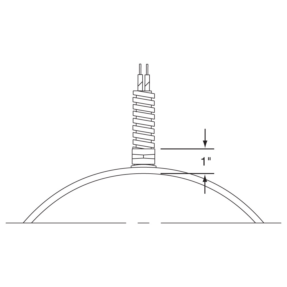
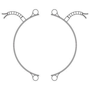
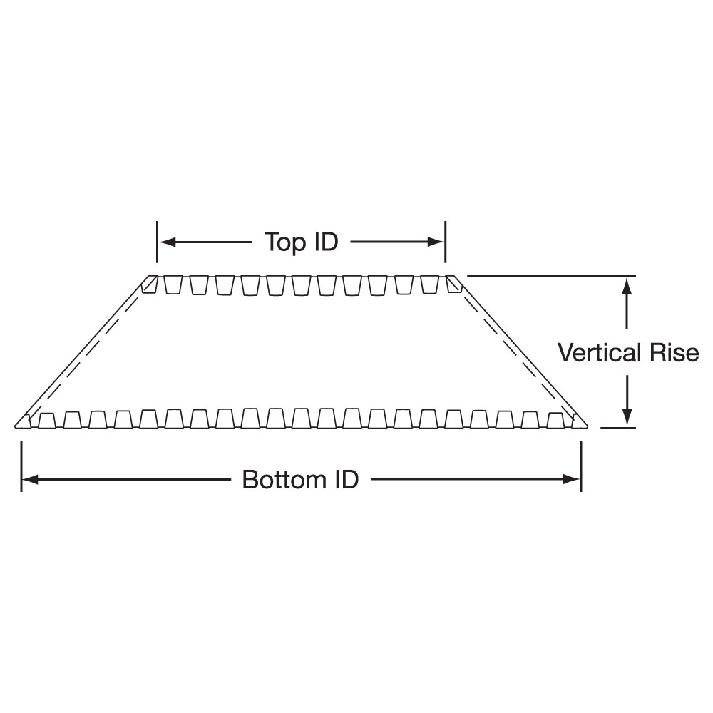
Partial coverage band heaters are normally required when holes and cutouts will not allow the heater to sufficiently clear the machine obstructions. The preferred method of construction is the Two-Piece Band Heater with Built-In Brackets as illustrated. The heater is screwed down to the cylinder at the ends and the built-in Low Thermal Expansion Strap pulls the heater tightly against the cylinder being heated. The standard center of hole to edge of heater dimension is 1/4″. When ordering, please provide the angle of coverage from center to center of the mounting screw holes as shown.
Type NS: Partial Coverage Band with Built-In Brackets (2 Piece)
Partial coverage band heaters are normally required when holes and cutouts will not allow the heater to sufficiently clear the machine obstructions. The preferred method of construction is the Two-Piece Band Heater with Built-In Brackets as illustrated. The heater is screwed down to the cylinder at the ends and the built-in Low Thermal Expansion Strap pulls the heater tightly against the cylinder being heated. The standard center of hole to edge of heater dimension is 1/4″. When ordering, please provide the angle of coverage from center to center of the mounting screw holes as shown.
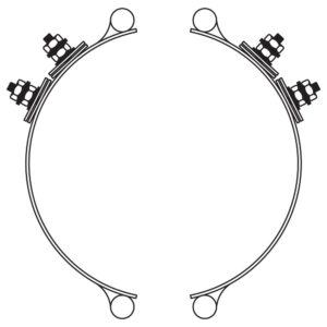
Angle of Coverage Drawing
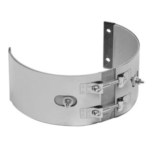
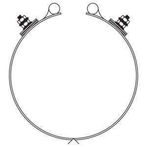
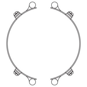
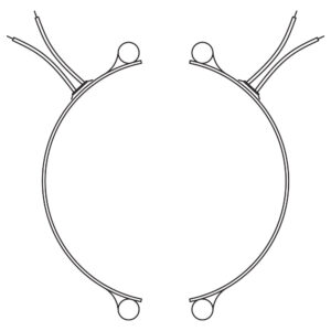
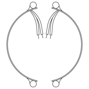
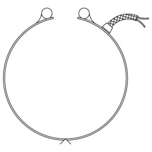
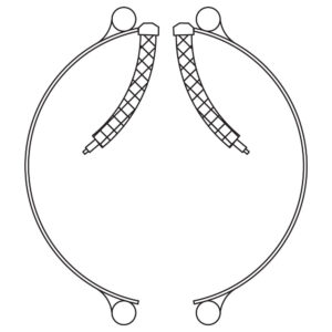
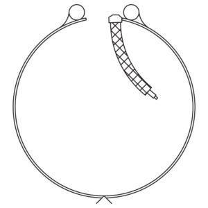
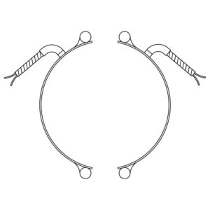
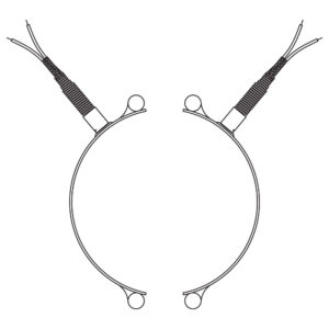
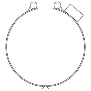
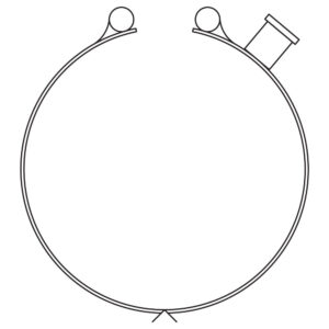
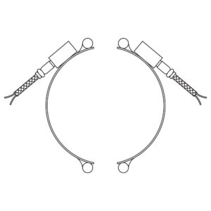
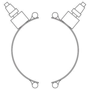
Type PS: Partial Coverage Band with Separate Strap (2 Piece)
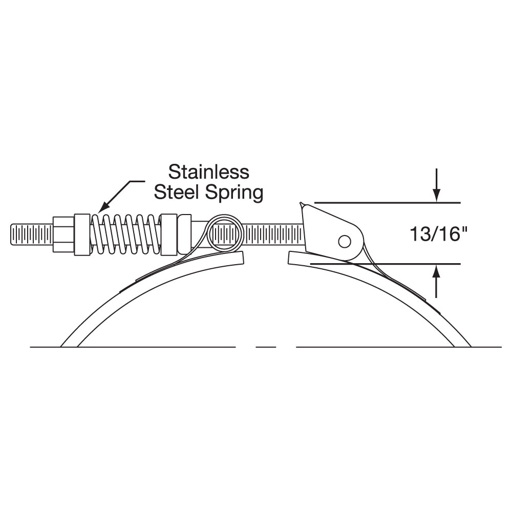
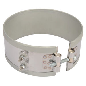
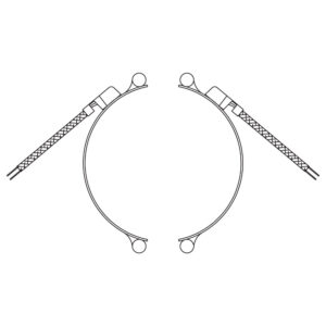
The alternate method of partial coverage construction is the One-Piece Band Heater with a separate Two-Piece Strap. The two-piece strap itself is screwed down at the padded ends, allowing the heater to float between the pads as illustrated. When the strap is tightened, it will pull the heater against the cylinder being heated. The standard center of hole to edge of heater dimension is 1/4″. When ordering, please provide the angle of coverage from center to center of the mounting screw holes as shown.
Type PS: Partial Coverage Band with Separate Strap (2 Piece)
The alternate method of partial coverage construction is the One-Piece Band Heater with a separate Two-Piece Strap. The two-piece strap itself is screwed down at the padded ends, allowing the heater to float between the pads as illustrated. When the strap is tightened, it will pull the heater against the cylinder being heated. The standard center of hole to edge of heater dimension is 1/4″. When ordering, please provide the angle of coverage from center to center of the mounting screw holes as shown.
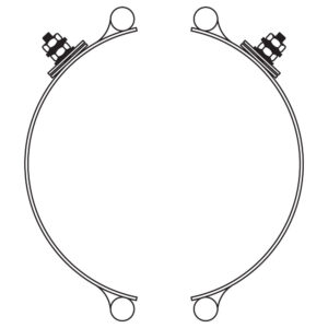
Angle of Coverage Drawing
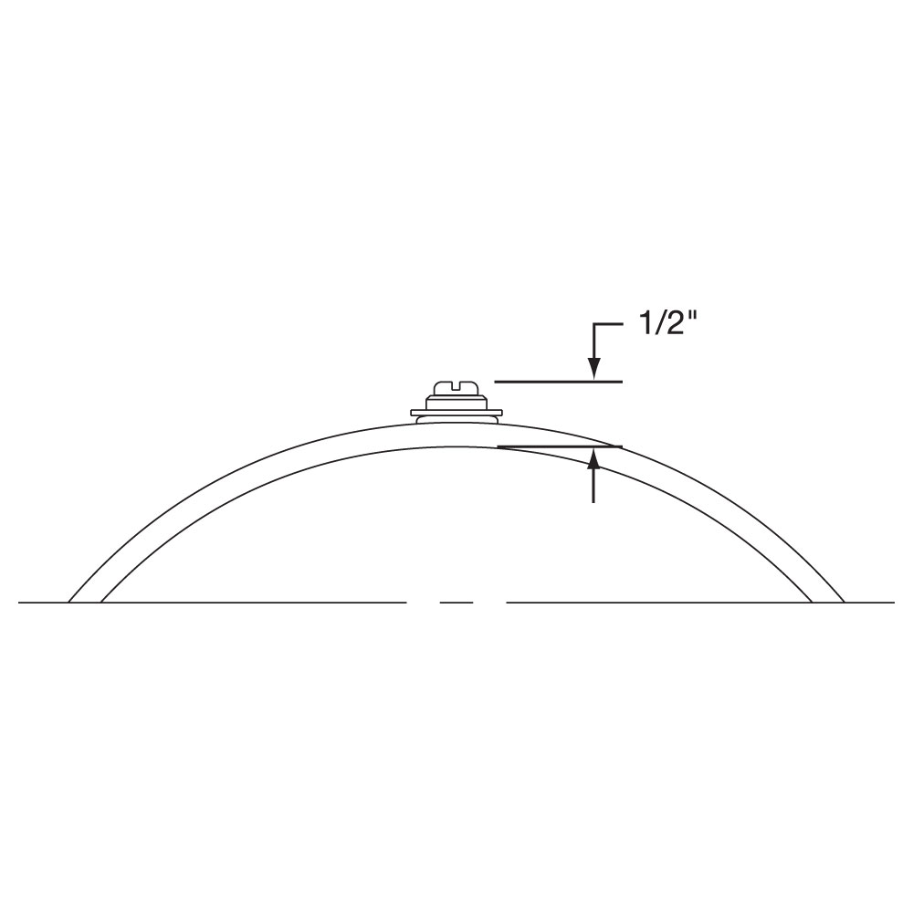
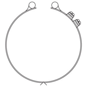
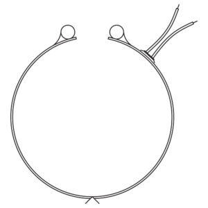
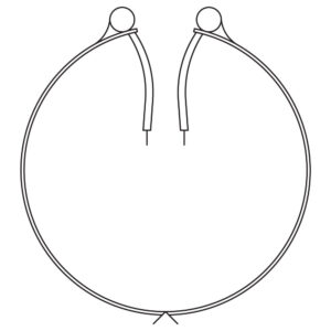
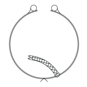
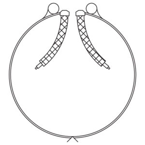
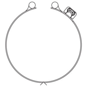
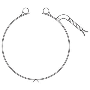
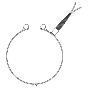
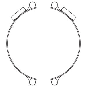
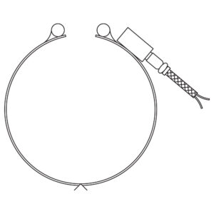
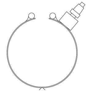
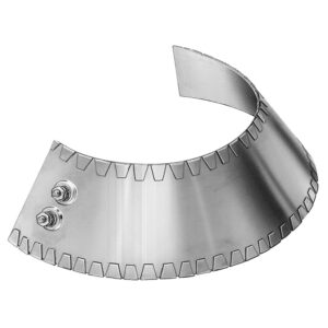
Type NB: Partial Coverage Band with Built-In Strap Clamping (1-Piece)
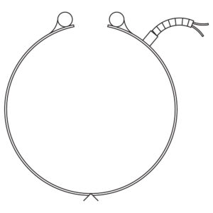
Another alternate method of partial coverage construction. The one piece with clamp screws on both sides allows it to be secured to anchor points on either side of a barrel without drilling holes into the barrel.
Type NB: Partial Coverage Band with Built-In Strap Clamping (1-Piece)
Another alternate method of partial coverage construction. The one piece with clamp screws on both sides allows it to be secured to anchor points on either side of a barrel without drilling holes into the barrel.
Type NB Angle of Coverage Drawing
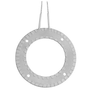
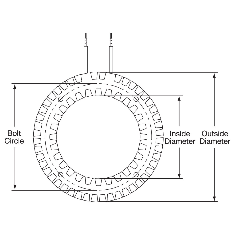
Type RNB: Reverse Band Constuction with Bracket Clamping (1-Piece)
This construction style is used to heat cylindrical surfaces from the inside on heaters 5-1/2″ diameter and larger.
Type RNB: Reverse Band Constuction with Bracket Clamping (1-Piece)
This construction style is used to heat cylindrical surfaces from the inside on heaters 5-1/2″ diameter and larger.
Limitations Inside Diameter Range: 5-1/2″ (139.7 mm) to 10″ (254.0 mm) Width Range: 1″ (25.4 mm) to 3-1/2″ (88.9 mm) Maximum Voltage: 240VAC
For ID’s greater than 10″ see Type RNS.
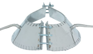
Type RNS: Reverse Band Construction with Bracket Clamping (2-Piece)
This construction style is used to heat cylindrical surfaces from the inside on heaters 10″ diameter and larger.
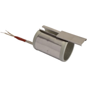
Type RTWL: Reverse Band Construction with Wedge Lock Clamping (1-Piece)
This construction style is used to heat cylindrical surfaces from the inside on heaters less than 5″ outside diameter.
Limitations Inside Diameter Range: 5-1/2″ (139.7 mm) to 20″ (508 mm) Width Range: 1″ (25.4 mm) to 3-1/2″ (88.9 mm) Maximum Voltage: 240VAC
📦
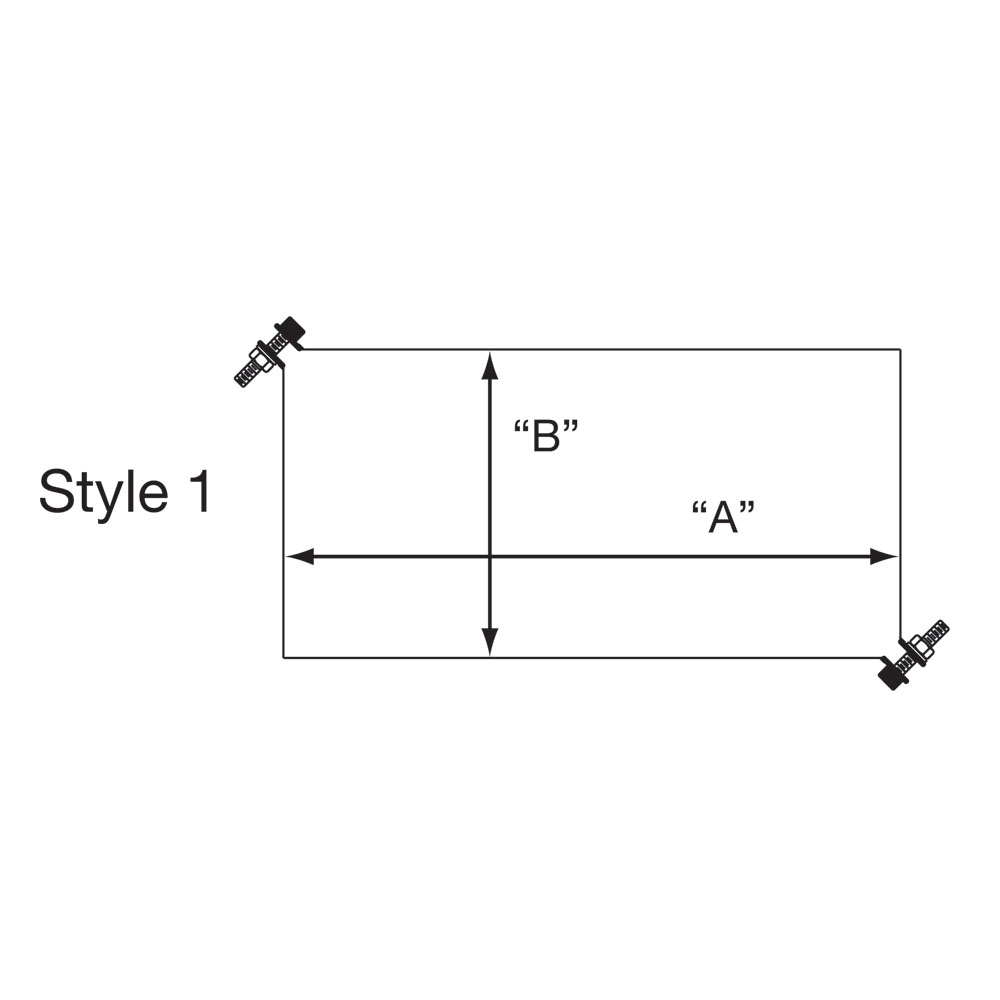
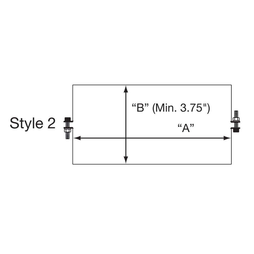
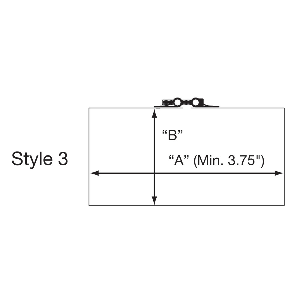
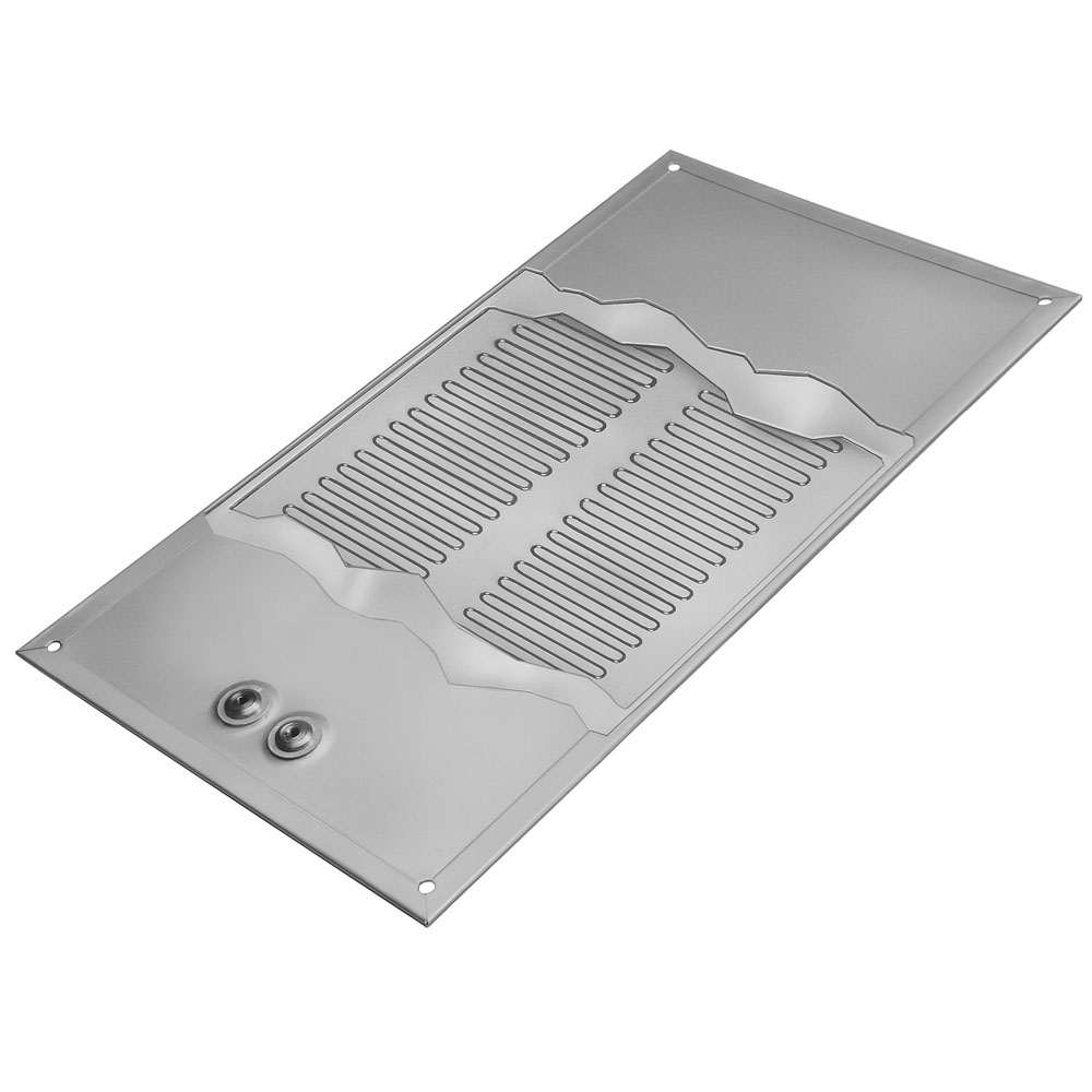
Square or Rectangular Shape
Square or Rectangular band heaters are normally used for heating dies on plastic extruders, or the barrels of twin screw extruders. They can be made in either one- or two-piece construction but two-piece construction with Style 1 Clamping (see below) is recommended.
Square or Rectangular band heaters are normally used for heating dies on plastic extruders, or the barrels of twin screw extruders. They can be made in either one- or two-piece construction but two-piece construction with Style 1 Clamping (see below) is recommended.
Limitations Width Range: 1″ to 3-1/2″ (25.4 – 88.9 mm)
Style 1 for 2-Piece Heaters (Recommended): bent-up flange clamping at the corners provides the most uniform clamping force and should be used whenever possible. Maximum Recommended Watt Density: 25 w/in2
Style 2 for 2-Piece Heaters: bent-up flange clamping or built-in strap brackets at the sides requires a minimum “B” dimension of 3.75″ (95.3 mm). Maximum Recommended Watt Density: 20 w/in2
Style 3 for 1-Piece Heaters: bent-up flange clamping or built-in strap brackets at the sides requires a minimum “A” dimension of 3.75″ (95.3 mm). Maximum Recommended Watt Density: 25 w/in2
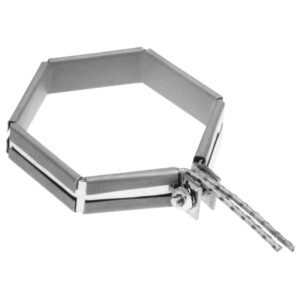
Hexagon Shape
Hexagon shaped band heaters are used on the hex shaped portion of the nozzle on injection molding machines. These types of heaters are strictly made to customer specifications with bent-up flange clamping only.
Hexagon shaped band heaters are used on the hex shaped portion of the nozzle on injection molding machines. These types of heaters are strictly made to customer specifications with bent-up flange clamping only.
Style 1for 2-piece heaters: bent-up flange clamping at the corners provides the most uniform clamping force and should be used whenever possible. Maximum Recommended Watt Density: 25 w/in2
Style 2for 2-piece heaters: bent-up flange clamping or built-in strap brackets at the sides requires a minimum “B” dimension of 3.75″ (95.3 mm).
Maximum Recommended Watt Density: 20 w/in2
Style 3 for 1-piece heaters: bent-up flange clamping or built-in strap brackets at the sides requires a minimum “A” dimension of 3.75″ (95.3 mm). Maximum Recommended Watt Density: 25 w/in2
Clamping Options
No options available for this section based on your selections
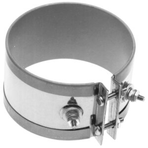
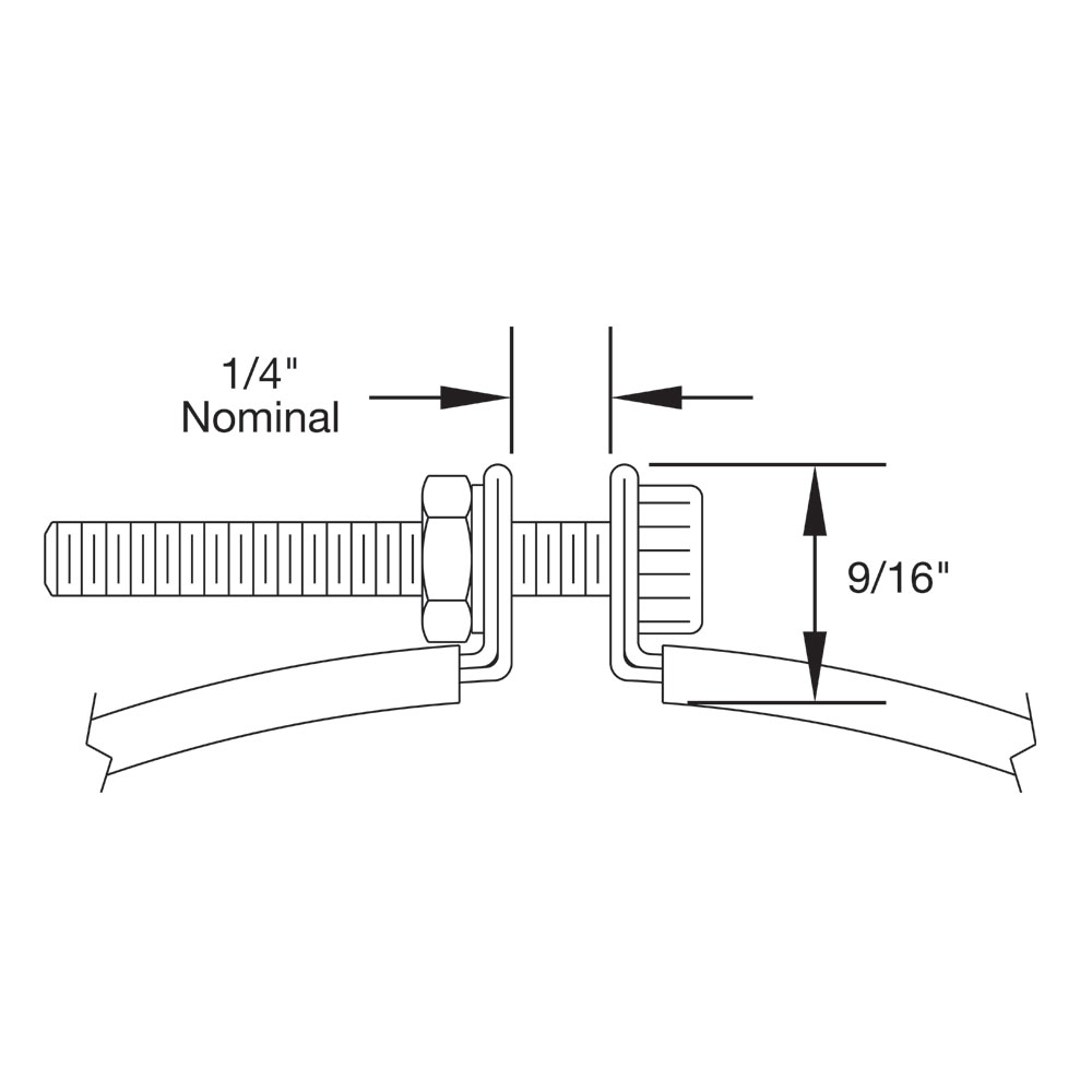
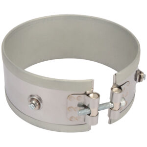
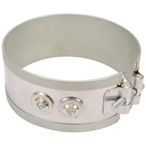
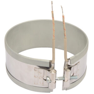
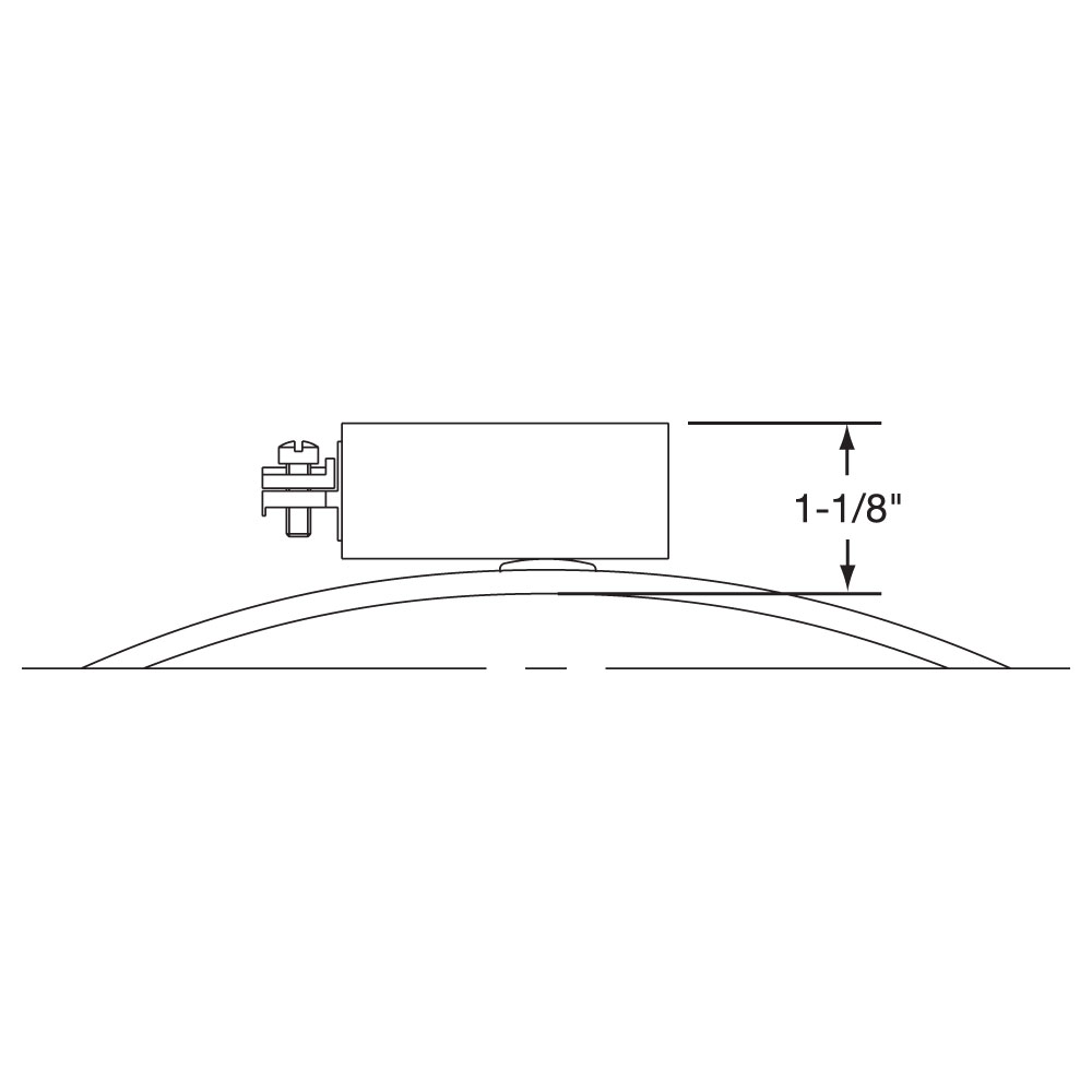
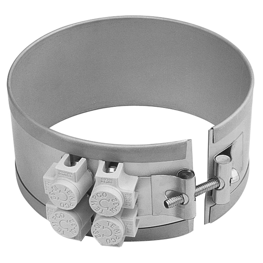
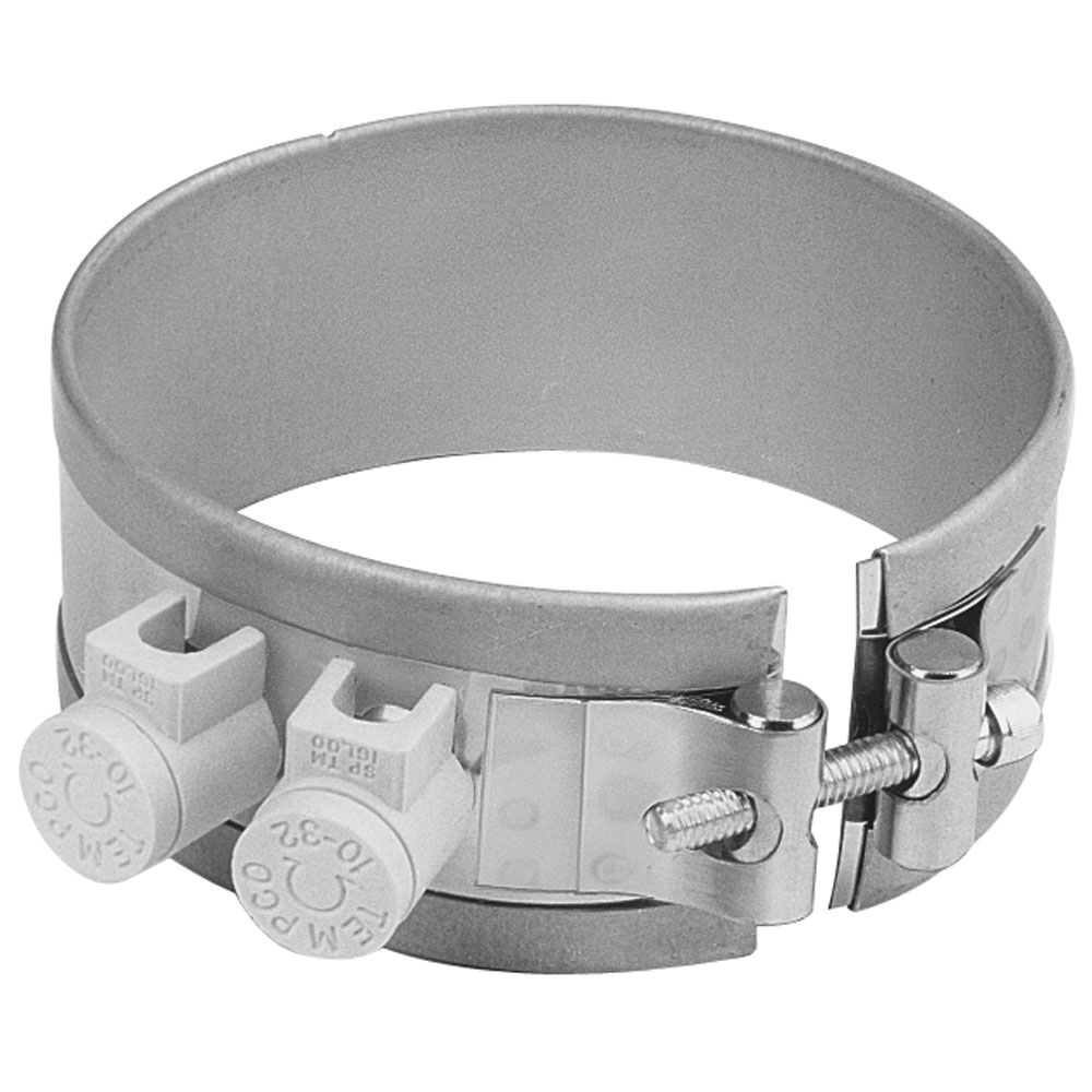
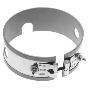
Type NB: Standard Built-In Strap Clamping (Low Thermal Expansion), One-Piece Band
The Built-In Strap eliminates the use of awkward-to-handle separate straps, providing more drawing power than any other type of clamping system. The Duraband with Built-In Strap is standard on many designs.
Type NB: Standard Built-In Strap Clamping (Low Thermal Expansion), One-Piece Band
The Built-In Strap eliminates the use of awkward-to-handle separate straps, providing more drawing power than any other type of clamping system. The Duraband with Built-In Strap is standard on many designs.
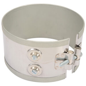
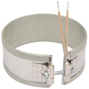
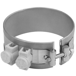
Type NS: Standard Built-In Strap Clamping (Low Thermal Expansion), Two-Piece Band
The Built-In Strap eliminates the use of awkward-to-handle separate straps, providing more drawing power than any other type of clamping system. The Duraband with Built-In Strap is standard on many designs.
Type NS: Standard Built-In Strap Clamping (Low Thermal Expansion), Two-Piece Band
The Built-In Strap eliminates the use of awkward-to-handle separate straps, providing more drawing power than any other type of clamping system. The Duraband with Built-In Strap is standard on many designs.
Type NE: Standard Built-In Strap Clamping (Low Thermal Expansion), One-Piece Expandable Band
The Built-In Strap eliminates the use of awkward-to-handle separate straps, providing more drawing power than any other type of clamping system. The Duraband with Built-In Strap is standard on many designs.
Type NE: Standard Built-In Strap Clamping (Low Thermal Expansion), One-Piece Expandable Band
The Built-In Strap eliminates the use of awkward-to-handle separate straps, providing more drawing power than any other type of clamping system. The Duraband with Built-In Strap is standard on many designs.
Wedge Lock clamping is designed for applications where mounting space is severely limited. It lends itself mainly to small diameter nozzle heaters.
Limitations
Minimum Inside Diameter: 1″ (25.4 mm)
Minimum Width: 1″ (25.4 mm)
Maximum Width: 3-1/2″ (88.9 mm)
Type SB: Separate Straps, One-Piece Band
The Separate Strap clamping is available with any screw or lead termination and construction variation. It is strongly recommended that the Duraband with Built-In Strap design be used whenever possible because it provides more drawing power than any other type of clamping system.
The Separate Strap clamping is available with any screw or lead termination and construction variation. It is strongly recommended that the Duraband with Built-In Strap design be used whenever possible because it provides more drawing power than any other type of clamping system.
The Separate Strap clamping is available with any screw or lead termination and construction variation. It is strongly recommended that the Duraband with Built-In Strap design be used whenever possible because it provides more drawing power than any other type of clamping system.
The Separate Strap clamping is available with any screw or lead termination and construction variation. It is strongly recommended that the Duraband with Built-In Strap design be used whenever possible because it provides more drawing power than any other type of clamping system.
Type SE: Separate Straps, One-Piece Expandable Band
The Separate Strap clamping is available with any screw or lead termination and construction variation. It is strongly recommended that the Duraband with Built-In Strap design be used whenever possible because it provides more drawing power than any other type of clamping system.
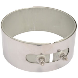
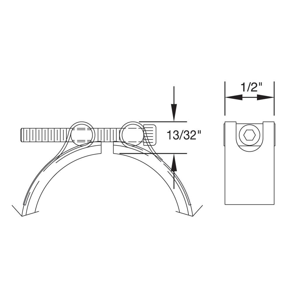
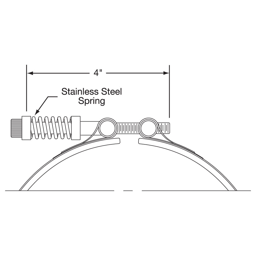
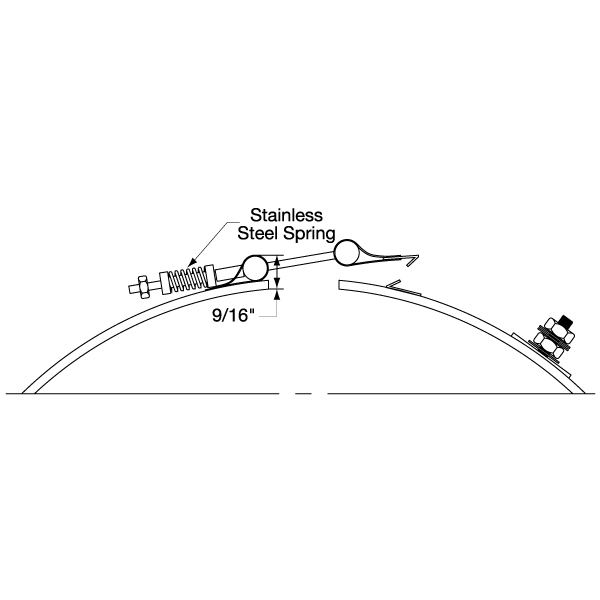
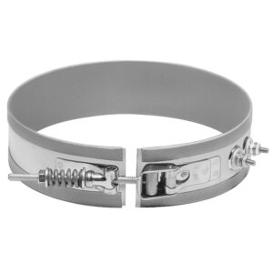
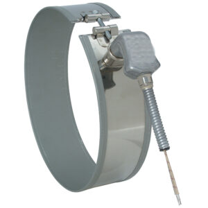
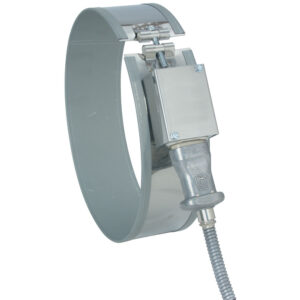
Type SL: Spring Loaded with Built-In Bracket, One-Piece Band
The Heavy Duty Stainless Steel Spring with Built-In Bracket is a variation on the basic Duraband design. It is available with any screw or lead termination and construction variation. It is recommended for heaters over 12″ in diameter, and for any diameter heater used in the vertical position, to prevent the heater from slipping off the machine. The springs provide constant tension, therefore maintaining optimum surface contact against the cylinder being heated.
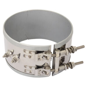
Type NSL: Spring Loaded with Built-In Bracket, Two-Piece Band
The Heavy Duty Stainless Steel Spring with Built-In Bracket is a variation on the basic Duraband design. It is available with any screw or lead termination and construction variation. It is recommended for heaters over 12″ in diameter, and for any diameter heater used in the vertical position, to prevent the heater from slipping off the machine. The springs provide constant tension, therefore maintaining optimum surface contact against the cylinder being heated.
Limitations
Minimum Inside Diameter: 4″ (101.6 mm)
Minimum Width: 1-1/4″ (31.8 mm)
Note: The number of straps is dependent on heater width. Tempco recommends the use of the largest bolt size that clearance allows.
Type NEL: Spring Loaded with Built-In Bracket, One-Piece Expandable Band
The Heavy Duty Stainless Steel Spring with Built-In Bracket is a variation on the basic Duraband design. It is available with any screw or lead termination and construction variation. It is recommended for heaters over 12″ in diameter, and for any diameter heater used in the vertical position, to prevent the heater from slipping off the machine. The springs provide constant tension, therefore maintaining optimum surface contact against the cylinder being heated.
Limitations
Minimum Inside Diameter: 4″ (101.6 mm)
Minimum Width: 1-1/4″ (31.8 mm)
Note: The number of straps is dependent on heater width. Tempco recommends the use of the largest bolt size that clearance allows.
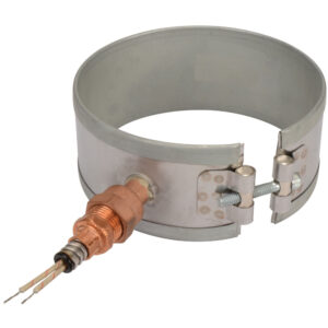
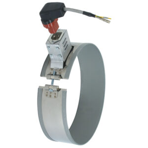
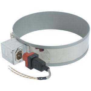
Type SLQD: Spring-Loaded Quick Disconnect, One-Piece Band
This construction style is a hybrid between the Spring Loaded Clamp with Built-In Bracket and the Latch and Trunnion style clamping. Utilizing a built in bracket and heavy duty flanges, this clamping style is durable and easy to work with in the field. The spring provides relief for thermal expansion and provides strong clamping for the band. This clamping style is available with either lead or screw terminal type terminations.
Type NSLQD: Spring-Loaded Quick Disconnect, Two-Piece Band
This construction style is a hybrid between the Spring Loaded Clamp with Built-In Bracket and the Latch and Trunnion style clamping. Utilizing a built in bracket and heavy duty flanges, this clamping style is durable and easy to work with in the field. The spring provides relief for thermal expansion and provides strong clamping for the band. This clamping style is available with either lead or screw terminal type terminations.
Type NELQD: Spring-Loaded Quick Disconnect, One-Piece Expandable Band
This construction style is a hybrid between the Spring Loaded Clamp with Built-In Bracket and the Latch and Trunnion style clamping. Utilizing a built in bracket and heavy duty flanges, this clamping style is durable and easy to work with in the field. The spring provides relief for thermal expansion and provides strong clamping for the band. This clamping style is available with either lead or screw terminal type terminations.
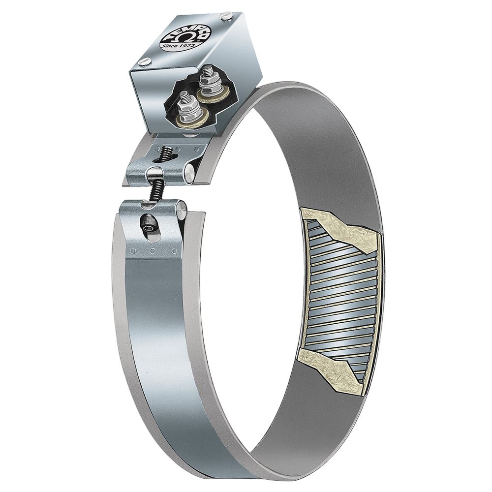
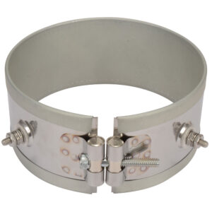
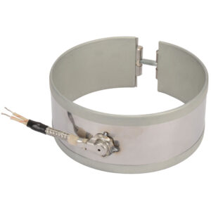
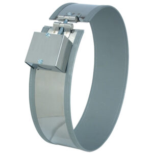
The Latch and Trunnion Clamping System is available with any screw or lead termination and construction variation. It is ideal in absorbing thermal expansion due to the spring loading on the screws. The latch fully opens, facilitating installation on large diameter cylinders. The outer sheath is made from a Low Thermal Expansion alloy.
The Latch and Trunnion Clamping System is available with any screw or lead termination and construction variation. It is ideal in absorbing thermal expansion due to the spring loading on the screws. The latch fully opens, facilitating installation on large diameter cylinders. The outer sheath is made from a Low Thermal Expansion alloy.
Note: The number of straps is dependent on heater width. Tempco recommends the use of the largest bolt size that clearance allows.
Type LS: Latch and Trunnion, Two-Piece Band
The Latch and Trunnion Clamping System is available with any screw or lead termination and construction variation. It is ideal in absorbing thermal expansion due to the spring loading on the screws. The latch fully opens, facilitating installation on large diameter cylinders. The outer sheath is made from a Low Thermal Expansion alloy.
The Latch and Trunnion Clamping System is available with any screw or lead termination and construction variation. It is ideal in absorbing thermal expansion due to the spring loading on the screws. The latch fully opens, facilitating installation on large diameter cylinders. The outer sheath is made from a Low Thermal Expansion alloy.
Type LE: Latch and Trunnion, One-Piece Expandable Band
The Latch and Trunnion Clamping System is available with any screw or lead termination and construction variation. It is ideal in absorbing thermal expansion due to the spring loading on the screws. The latch fully opens, facilitating installation on large diameter cylinders. The outer sheath is made from a Low Thermal Expansion alloy.
The Bent-Up Flange clamping is available with any screw or lead termination and construction variation. The outer sheath is made from a Low Thermal Expansion alloy. The Bent-Up Flange design is best suited for narrow band heaters with small diameters.
The Bent-Up Flange clamping is available with any screw or lead termination and construction variation. The outer sheath is made from a Low Thermal Expansion alloy. The Bent-Up Flange design is best suited for narrow band heaters with small diameters.
The Bent-Up Flange clamping is available with any screw or lead termination and construction variation. The outer sheath is made from a Low Thermal Expansion alloy. The Bent-Up Flange design is best suited for narrow band heaters with small diameters.
The Bent-Up Flange clamping is available with any screw or lead termination and construction variation. The outer sheath is made from a Low Thermal Expansion alloy. The Bent-Up Flange design is best suited for narrow band heaters with small diameters.
Type FE: Bent-Up Flange (Ears), One-Piece Expandable Band
The Bent-Up Flange clamping is available with any screw or lead termination and construction variation. The outer sheath is made from a Low Thermal Expansion alloy. The Bent-Up Flange design is best suited for narrow band heaters with small diameters.
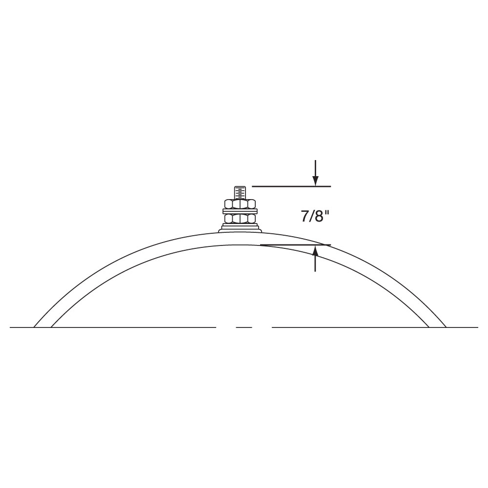
Standard Termination Location: each side of gap; center of width
Minimum Inside Diameter: 2″ (50.8 mm)
Minimum Width: 7/8″ (22.2 mm)
Post Terminals: 10-32 standard except 8-32 on < 1" wide heaters & heaters with ID < 3"
Max. Volts/Amps: 480VAC/ 25A (10-32) or 20A (8-32)
Available on any clamping or construction variation, the specially designed Stainless Steel Power Terminals are internally connected to the heater and are resistant to over-torquing. The screw terminals are virtually unbreakable. Secure tightening of the electrical connections is essential for safety and long heater life.
Considered standard on most band heaters unless otherwise specified.
Type T1: Screw Terminals, Two-Piece Band
Standard Termination Location: next to gaps on each half; center of width
Minimum Inside Diameter: 2″ (50.8 mm)
Minimum Width: 7/8″ (22.2 mm)
Post Terminals: 10-32 standard except 8-32 on < 1" wide heaters & heaters with ID < 3"
Max. Volts/Amps: 480VAC/25A (10-32) or 20A (8-32) each half
Standard Termination Location: next to gaps on each half; center of width
Minimum Inside Diameter: 2″ (50.8 mm)
Minimum Width: 7/8″ (22.2 mm)
Post Terminals: 10-32 standard except 8-32 on < 1" wide heaters & heaters with ID < 3"
Max. Volts/Amps: 480VAC/25A (10-32) or 20A (8-32) each half
Available on any clamping or construction variation, the specially designed Stainless Steel Power Terminals are internally connected to the heater and are resistant to over-torquing. The screw terminals are virtually unbreakable. Secure tightening of the electrical connections is essential for safety and long heater life.
Considered standard on most band heaters unless otherwise specified.
Type T1: Screw Terminals, One-Piece Expandable Band
Standard Termination Location: each side of gap; center of width
Minimum Inside Diameter: 2-1/2″ (63.5 mm)
Minimum Width: 1-1/4″ (31.8 mm)
Post Terminals: 10-32 standard except 8-32 on heaters with ID < 3"
Max. Volts/Amps: 480VAC/ 25A (10-32) or 20A (8-32)
Available on any clamping or construction variation, the specially designed Stainless Steel Power Terminals are internally connected to the heater and are resistant to over-torquing. The screw terminals are virtually unbreakable. Secure tightening of the electrical connections is essential for safety and long heater life.
Considered standard on most band heaters unless otherwise specified.
Note: The number of weld-on brackets is dependent on heater width. Tempco recommends the use of the largest bolt size that clearance allows.
Type T2: Screw Terminals, One-Piece Band
Standard Termination Location: next to gap; center of width
Minimum Inside Diameter: 2″ (50.8 mm)
Minimum Width: 7/8″ (22.2 mm)
Post Terminals: 10-32 standard except 8-32 on < 1" wide heaters & heaters with ID < 3"
Maximum Volts/Amps: 480VAC/ 25A (10-32) or 20A (8-32)
Standard Termination Location: next to gap; center of width
Minimum Inside Diameter: 2″ (50.8 mm)
Minimum Width: 7/8″ (22.2 mm)
Post Terminals: 10-32 standard except 8-32 on < 1" wide heaters & heaters with ID < 3"
Maximum Volts/Amps: 480VAC/ 25A (10-32) or 20A (8-32)
Available on any clamping or construction variation, the specially designed Stainless Steel Power Terminals are internally connected to the heater and are resistant to over-torquing. The screw terminals are virtually unbreakable. Secure tightening of the electrical connections is essential for safety and long heater life.
Recommended for narrow band heaters where screw terminals are preferred or the C2 terminal box protection is required.
Note: The number of weld-on brackets is dependent on heater width. Tempco recommends the use of the largest bolt size that clearance allows.
Type T2: Screw Terminals, Two-Piece Band
Standard Termination Location: next to same gap on each half; center of width
Minimum Inside Diameter: 2″ (50.8 mm)
Minimum Width: 7/8″ (22.2 mm)
Post Terminals: 10-32 standard except 8-32 on < 1" wide heaters & heaters with ID < 3"
Max. Volts/Amps: 480VAC/ 25A (10-32) or 20A (8-32) each half
Standard Termination Location: next to same gap on each half; center of width
Minimum Inside Diameter: 2″ (50.8 mm)
Minimum Width: 7/8″ (22.2 mm)
Post Terminals: 10-32 standard except 8-32 on < 1" wide heaters & heaters with ID < 3"
Max. Volts/Amps: 480VAC/ 25A (10-32) or 20A (8-32) each half
Available on any clamping or construction variation, the specially designed Stainless Steel Power Terminals are internally connected to the heater and are resistant to over-torquing. The screw terminals are virtually unbreakable. Secure tightening of the electrical connections is essential for safety and long heater life.
Recommended for narrow band heaters where screw terminals are preferred or the C2 terminal box protection is required.
Note: The number of weld-on brackets is dependent on heater width. Tempco recommends the use of the largest bolt size that clearance allows.
Type T2: Screw Terminals, One-Piece Expandable Band
Standard Termination Location: next to gap; center of width
Minimum Inside Diameter: 2-1/2″ (63.5 mm)
Minimum Width: 1-1/4″ (31.8 mm)
Post Terminals: 10-32 standard except 8-32 on heaters with ID < 3"
Max. Volts/Amps: 480VAC/ 25A (10-32) or 20A (8-32)
Available on any clamping or construction variation, the specially designed Stainless Steel Power Terminals are internally connected to the heater and are resistant to over-torquing. The screw terminals are virtually unbreakable. Secure tightening of the electrical connections is essential for safety and long heater life.
Recommended for narrow band heaters where screw terminals are preferred or the C2 terminal box protection is required.
Type T3: Screw Terminals, One-Piece Band
Standard Termination Location: next to gap; across center of width
Minimum Inside Diameter: 2″ (50.8 mm)
Minimum Width: 2″ (50.8 mm)
Post Terminals: 10-32 standard except 8-32 on 2″ to 2-1/2″ wide heaters & heaters with ID < 3"
Maximum Volts/Amps: 480VAC/25A (10-32) or 20A (8-32)
Standard Termination Location: next to gap; across center of width
Minimum Inside Diameter: 2″ (50.8 mm)
Minimum Width: 2″ (50.8 mm)
Post Terminals: 10-32 standard except 8-32 on 2″ to 2-1/2″ wide heaters & heaters with ID < 3"
Maximum Volts/Amps: 480VAC/25A (10-32) or 20A (8-32)
Available on any clamping or construction variation, the specially designed Stainless Steel Power Terminals are internally connected to the heater and are resistant to over-torquing. The screw terminals are virtually unbreakable. Secure tightening of the electrical connections is essential for safety and long heater life.
The preferred design on band heaters over 3″ (76.2 mm) wide or when C3 terminal box is required
Type T3: Screw Terminals, Two-Piece Band
Standard Termination Location: next to same gap on each half; across center of width
Minimum Inside Diameter: 2″ (50.8 mm)
Minimum Width: 2″ (50.8 mm)
Post Terminals: 10-32 standard except 8-32 on 2″ to 2-1/2″ wide heaters & heaters with ID < 3"
Maximum Volts/Amps: 480VAC/ 25A (10-32) or 20A (8-32) each half
Available on any clamping or construction variation, the specially designed Stainless Steel Power Terminals are internally connected to the heater and are resistant to over-torquing. The screw terminals are virtually unbreakable. Secure tightening of the electrical connections is essential for safety and long heater life.
The preferred design on band heaters over 3″ (76.2 mm) wide or when C3 terminal box is required
Type T3: Screw Terminals, One-Piece Expandable Band
Standard Termination Location: next to gap; across center of width
Minimum Inside Diameter: 2-1/2″ (63.5 mm)
Minimum Width: 2″ (50.8 mm)
Post Terminals: 10-32 standard except 8-32 on 2″ to 2-1/2″ wide heaters & heaters with ID < 3"
Maximum Volts/Amps: 480VAC/ 25A (10-32) or 20A (8-32)
Available on any clamping or construction variation, the specially designed Stainless Steel Power Terminals are internally connected to the heater and are resistant to over-torquing. The screw terminals are virtually unbreakable. Secure tightening of the electrical connections is essential for safety and long heater life.
The preferred design on band heaters over 3″ (76.2 mm) wide or when C3 terminal box is required
Type B1: Button Terminals, One-Piece Band
Standard Termination Location: each side of gap; center of width
Minimum Inside Diameter: 2″ (50.8 mm)
Minimum Width: 1-1/2″ (38.1 mm)
Screw Size: 10-32 standard except 6-32 on IDs < 5"
Standard Termination Location: each side of gap; center of width
Minimum Inside Diameter: 2″ (50.8 mm)
Minimum Width: 1-1/2″ (38.1 mm)
Screw Size: 10-32 standard except 6-32 on IDs < 5"
Maximum Volts: 480VAC
Maximum Amps: 25A (10-32) or 20A (6-32)
Available on any clamping or construction variation, the specially designed Stainless Steel Button Terminals are internally connected to the heater and are resistant to over-torquing while offering a low profile for tight spaces. They are virtually unbreakable. Secure tightening of the electrical connections is essential for safety and long heater life.
Type B1: Button Terminals, Two-Piece Band
Standard Termination Location: next to gaps on each half; center of width
Minimum Inside Diameter: 2″ (50.8 mm)
Minimum Width: 1-1/2″ (38.1 mm)
Screw Size: 10-32 standard except 6-32 on IDs < 5"
Maximum Volts/Amps: 480VAC/ 25A (10-32) or 20A (6-32) each half
Standard Termination Location: next to gaps on each half; center of width
Minimum Inside Diameter: 2″ (50.8 mm)
Minimum Width: 1-1/2″ (38.1 mm)
Screw Size: 10-32 standard except 6-32 on IDs < 5"
Maximum Volts/Amps: 480VAC/ 25A (10-32) or 20A (6-32) each half
Available on any clamping or construction variation, the specially designed Stainless Steel Button Terminals are internally connected to the heater and are resistant to over-torquing while offering a low profile for tight spaces. They are virtually unbreakable. Secure tightening of the electrical connections is essential for safety and long heater life.
Type B1: Button Terminals, One-Piece Expandable Band
Standard Termination Location: each side of gap; center of width
Minimum Inside Diameter: 2-1/2″ (63.5 mm)
Minimum Width: 1-1/2″ (38.1 mm)
Screw Size: 10-32 standard except 6-32 on IDs < 5"
Maximum Volts/Amps: 480VAC/ 25A (10-32) or 20A (6-32)
Type B1: Button Terminals, One-Piece Expandable Band
Standard Termination Location: each side of gap; center of width
Minimum Inside Diameter: 2-1/2″ (63.5 mm)
Minimum Width: 1-1/2″ (38.1 mm)
Screw Size: 10-32 standard except 6-32 on IDs < 5"
Maximum Volts/Amps: 480VAC/ 25A (10-32) or 20A (6-32)
Available on any clamping or construction variation, the specially designed Stainless Steel Button Terminals are internally connected to the heater and are resistant to over-torquing while offering a low profile for tight spaces. They are virtually unbreakable. Secure tightening of the electrical connections is essential for safety and long heater life.
Type B2: Button Terminals, One-Piece Band
Standard Termination Location: next to gap; center of width
Minimum Inside Diameter: 2″ (50.8 mm)
Minimum Width: 1-1/2″ (38.1 mm)
Screw Size: 10-32 standard except 6-32 on IDs < 5"
Standard Termination Location: next to gap; center of width
Minimum Inside Diameter: 2″ (50.8 mm)
Minimum Width: 1-1/2″ (38.1 mm)
Screw Size: 10-32 standard except 6-32 on IDs < 5"
Maximum Volts: 480VAC
Maximum Amps: 25A (10-32) or 20A (6-32)
Available on any clamping or construction variation, the specially designed Stainless Steel Button Terminals are internally connected to the heater and are resistant to over-torquing while offering a low profile for tight spaces. They are virtually unbreakable. Secure tightening of the electrical connections is essential for safety and long heater life.
Type B2: Button Terminals, Two-Piece Band
Standard Termination Location: next to same gap on each half; center of width
Minimum Inside Diameter: 2″ (50.8 mm
Minimum Width: 1-1/2″ (38.1 mm)
Screw Size: 10-32 standard except 6-32 on IDs < 5"
Maximum Volts/Amps: 480VAC/ 25A (10-32) or 20A (6-32) each half
Standard Termination Location: next to same gap on each half; center of width
Minimum Inside Diameter: 2″ (50.8 mm
Minimum Width: 1-1/2″ (38.1 mm)
Screw Size: 10-32 standard except 6-32 on IDs < 5"
Maximum Volts/Amps: 480VAC/ 25A (10-32) or 20A (6-32) each half
Available on any clamping or construction variation, the specially designed Stainless Steel Button Terminals are internally connected to the heater and are resistant to over-torquing while offering a low profile for tight spaces. They are virtually unbreakable. Secure tightening of the electrical connections is essential for safety and long heater life.
Type B2: Button Terminals, One-Piece Expandable Band
Standard Termination Location: next to gap; center of width
Minimum Inside Diameter: 2-1/2″ (63.5 mm)
Minimum Width: 1-1/2″ (38.1 mm)
Screw Size: 10-32 standard except 6-32 on IDs < 5"
Maximum Volts/Amps: 480VAC/ 25A (10-32) or 20A (6-32)
Type B2: Button Terminals, One-Piece Expandable Band
Standard Termination Location: next to gap; center of width
Minimum Inside Diameter: 2-1/2″ (63.5 mm)
Minimum Width: 1-1/2″ (38.1 mm)
Screw Size: 10-32 standard except 6-32 on IDs < 5"
Maximum Volts/Amps: 480VAC/ 25A (10-32) or 20A (6-32)
Available on any clamping or construction variation, the specially designed Stainless Steel Button Terminals are internally connected to the heater and are resistant to over-torquing while offering a low profile for tight spaces. They are virtually unbreakable. Secure tightening of the electrical connections is essential for safety and long heater life.
Type B3: Button Terminals, One-Piece Band
Standard Termination Location: next to gap; across center of width
Minimum Inside Diameter: 2″ (50.8 mm)
Minimum Width: 2-3/8″ (60.3 mm)
Screw Size: 10-32 standard except 6-32 on IDs < 5"
Standard Termination Location: next to gap; across center of width
Minimum Inside Diameter: 2″ (50.8 mm)
Minimum Width: 2-3/8″ (60.3 mm)
Screw Size: 10-32 standard except 6-32 on IDs < 5"
Maximum Volts: 480VAC
Maximum Amps: 25A (10-32) or 20A (6-32)
Available on any clamping or construction variation, the specially designed Stainless Steel Button Terminals are internally connected to the heater and are resistant to over-torquing while offering a low profile for tight spaces. They are virtually unbreakable. Secure tightening of the electrical connections is essential for safety and long heater life.
Type B3: Button Terminals, Two-Piece Band
Standard Termination Location: next to same gap on each half; across center of width
Minimum Inside Diameter: 2″ (50.8 mm)
Minimum Width: 2-3/8″ (60.3 mm)
Screw Size: 10-32 standard except 6-32 on IDs < 5"
Maximum Volts/Amps: 480VAC/ 25A (10-32) or 20A (6-32) each half
Standard Termination Location: next to same gap on each half; across center of width
Minimum Inside Diameter: 2″ (50.8 mm)
Minimum Width: 2-3/8″ (60.3 mm)
Screw Size: 10-32 standard except 6-32 on IDs < 5"
Maximum Volts/Amps: 480VAC/ 25A (10-32) or 20A (6-32) each half
Available on any clamping or construction variation, the specially designed Stainless Steel Button Terminals are internally connected to the heater and are resistant to over-torquing while offering a low profile for tight spaces. They are virtually unbreakable. Secure tightening of the electrical connections is essential for safety and long heater life.
Type B3: Button Terminals, One-Piece Expandable Band
Standard Termination Location: next to gap; across center of width
Minimum Inside Diameter: 2-1/2″ (63.5 mm)
Minimum Width: 2-3/8″ (60.3 mm)
Screw Size: 10-32 standard except 6-32 on IDs < 5"
Maximum Volts/Amps: 480VAC/ 25A (10-32) or 20A (6-32)
Type B3: Button Terminals, One-Piece Expandable Band
Standard Termination Location: next to gap; across center of width
Minimum Inside Diameter: 2-1/2″ (63.5 mm)
Minimum Width: 2-3/8″ (60.3 mm)
Screw Size: 10-32 standard except 6-32 on IDs < 5"
Maximum Volts/Amps: 480VAC/ 25A (10-32) or 20A (6-32)
Available on any clamping or construction variation, the specially designed Stainless Steel Button Terminals are internally connected to the heater and are resistant to over-torquing while offering a low profile for tight spaces. They are virtually unbreakable. Secure tightening of the electrical connections is essential for safety and long heater life.
Type L1: Straight Lead Wires, One-Piece Band
Standard Termination Location: next to gap; center of width
Standard Termination Location: each side of gap; edge of width
Minimum Inside Diameter: 7/8″ (22.2 mm)
Minimum Width: 3/4″ (19.1 mmL
Maximum Volts: 480VAC
Maximum Amps: 12.5A
Available on any clamping or construction variation.
L2 is the preferred termination on all small diameter and small width band heaters. The standard flexible leads are 10″ long with 3″ of fiberglass sleeving.
Type L2: Straight Lead Wires, Two-Piece Band
Standard Termination Location: each side of each gap; edge of width
Standard Termination Location: each side of each gap; edge of width
Minimum Inside Diameter: 2″ (50.8 mm)
Minimum Width: 3/4″ (19.1 mm)
Maximum Volts: 480V each half
Maximum Amps: 12.5A each half
Available on any clamping or construction variation.
L2 is the preferred termination on all small diameter and small width band heaters. The standard flexible leads are 10″ long with 3″ of fiberglass sleeving.
Type L2: Straight Lead Wires, One-Piece Expandable Band
Standard Termination Location: each side of gap; edge of width
Available on any clamping or construction variation.
L2 is the preferred termination on all small diameter and small width band heaters. The standard flexible leads are 10″ long with 3″ of fiberglass sleeving.
Type L4: Straight Lead Wires, One-Piece Band
Standard Termination Location: same side of gap; edge of width
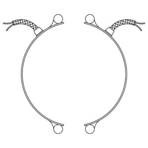
Type W1 & W1T: Straight Wire Braid Leads, One-Piece Band
Standard Termination Location: next to gap; center of width
Minimum Inside Diameter: 2″ (50.8 mm)
Minimum Width: 1″ (25.4 mm)
Maximum Volts: 480VAC
Maximum Amps: 12.5A
Available on any clamping or construction variation. Wire braid leads offer sharp bending not possible with armor cable.
W1 – Braided lead wire crimped in place for heaters under 2-1/2″ I.D. and/or under 1-1/4″ width. W1T – Braided lead wire attached with a threaded fitting for heaters with 2-1/2″ and over I.D. and 1-1/4″ and over width.
Type W1 & W1T:: Straight Wire Braid Leads, Two-Piece Band
Standard Termination Location: next to same gap on each half; center of width
Type W1 & W1T:: Straight Wire Braid Leads, Two-Piece Band
Standard Termination Location: next to same gap on each half; center of width
Minimum Inside Diameter: 2″ (50.8 mm)
Minimum Width: 1″ (25.4 mm)
Maximum Volts: 480VAC each half
Maximum Amps: 12.5A each half
Available on any clamping or construction variation. Wire braid leads offer sharp bending not possible with armor cable.
W1 – Braided lead wire crimped in place for heaters under 2-1/2″ I.D. and/or under 1-1/4″ width. W1T – Braided lead wire attached with a threaded fitting for heaters with 2-1/2″ and over I.D. and 1-1/4″ and over width.
Type W1 & W1T:: Straight Wire Braid Leads, One-Piece Expandable Band
Standard Termination Location: next to gap; center of width
Type W1 & W1T:: Straight Wire Braid Leads, One-Piece Expandable Band
Standard Termination Location: next to gap; center of width
Minimum Inside Diameter: 2-1/2″ (63.5 mm)
Minimum Width: 1-1/4″ (31.8 mm)
Maximum Volts: 480VAC
Maximum Amps: 12.5A
Available on any clamping or construction variation. Wire braid leads offer sharp bending not possible with armor cable.
W1 – Braided lead wire crimped in place for heaters under 2-1/2″ I.D. and/or under 1-1/4″ width. W1T – Braided lead wire attached with a threaded fitting for heaters with 2-1/2″ and over I.D. and 1-1/4″ and over width.
Type W2: Wire Braid Leads, One-Piece Band
Standard Termination Location: opposite the gap; edge of width
Standard Termination Location: opposite the gap; edge of width
Minimum Inside Diameter: 7/8″ (22.2 mm)
Minimum Width: 1-1/8″ (28.6 mm)
Maximum Volts: 480VAC
Maximum Amps: 12.5A
Available on any clamping or construction variation. Wire braid leads offer sharp bending not possible with armor cable.
The W2 wire braid exits at the middle of the segment on 1 and 2 piece designs and offset 1″ from the middle of the segmet for expandable designs.
Sleeving is used for additional protection.
The standard leads are 10″ of wire braid over 12″ of flexible leads with 3″ of fiberglass sleeving.
Type W2: Wire Braid Leads, Two-Piece Band
Standard Termination Location: center of each half; edge of width
Standard Termination Location: center of each half; edge of width
Minimum Inside Diameter: 2″ (50.8 mm)
Minimum Width: 1-1/8″ (28.6 mm)
Maximum Volts: 480VAC each half
Maximum Amps: 12.5A each half
Available on any clamping or construction variation. Wire braid leads offer sharp bending not possible with armor cable.
The W2 wire braid exits at the middle of the segment on 1 and 2 piece designs and offset 1″ from the middle of the segmet for expandable designs.
Sleeving is used for additional protection.
The standard leads are 10″ of wire braid over 12″ of flexible leads with 3″ of fiberglass sleeving.
Type W2: Wire Braid Leads, One-Piece Expandable Band
Standard Termination Location: opposite the gap offset 1″; edge of width
Type W2: Wire Braid Leads, One-Piece Expandable Band
Standard Termination Location: opposite the gap offset 1″; edge of width
Minimum Inside Diameter: 2-1/2″ (63.5 mm)
Minimum Width: 1-1/8″ (28.6 mm)
Maximum Volts: 480VAC
Maximum Amps: 12.5A
Available on any clamping or construction variation. Wire braid leads offer sharp bending not possible with armor cable.
The W2 wire braid exits at the middle of the segment on 1 and 2 piece designs and offset 1″ from the middle of the segmet for expandable designs.
Sleeving is used for additional protection.
The standard leads are 10″ of wire braid over 12″ of flexible leads with 3″ of fiberglass sleeving.
Type W3: Single Wire Braid Leads, One-Piece Band
Standard Termination Location: each side of gap; edge of width
Standard Termination Location: each side of gap; edge of width
Minimum Inside Diameter: 3/4″ (19.1 mm)
Minimum Width: 7/8″ (22.2 mm)
Maximum Volts: 480VAC
Maximum Amps: 12.5A
Available on any clamping or construction variation. Wire braid leads offer sharp bending not possible with armor cable.
Highly recommended for nozzle heating applications.
The standard leads are 10″ of wire braid over 12″ of flexible leads with 3″ of fiberglass sleeving.
Type W3: Single Wire Braid Leads, Two-Piece Band
Standard Termination Location: each side of each gap; edge of width
Standard Termination Location: each side of each gap; edge of width
Minimum Inside Diameter: 2″ (50.8 mm)
Minimum Width: 3/4″ (19.1 mm)
Maximum Volts: 480VAC each half
Maximum Amps: 12.5A each half
Available on any clamping or construction variation. Wire braid leads offer sharp bending not possible with armor cable.
Highly recommended for nozzle heating applications.
The standard leads are 10″ of wire braid over 12″ of flexible leads with 3″ of fiberglass sleeving.
Type W3: Single Wire Braid Leads, One-Piece Expandable Band
Standard Termination Location: each side of gap; edge of width
Type W3: Single Wire Braid Leads, One-Piece Expandable Band
Standard Termination Location: each side of gap; edge of width
Minimum Inside Diameter: 2-1/2″ (63.5 mm)
Minimum Width: 1-1/4″ (31.8 mm)
Maximum Volts: 480VAC
Maximum Amps: 12.5A
Available on any clamping or construction variation. Wire braid leads offer sharp bending not possible with armor cable.
Highly recommended for nozzle heating applications.
The standard leads are 10″ of wire braid over 12″ of flexible leads with 3″ of fiberglass sleeving.
Type W4: Wire Braid Leads On One Side, One-Piece Band
Standard Termination Location: next to gap; edge of width
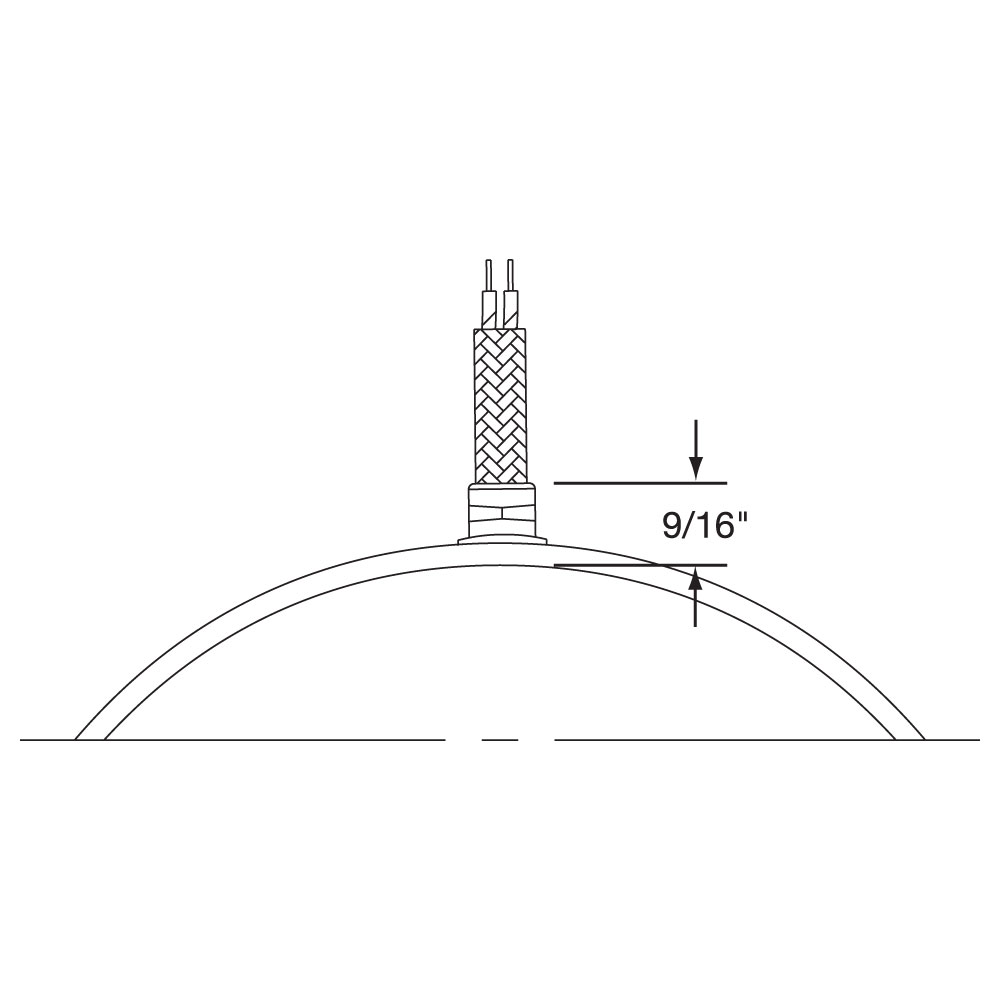
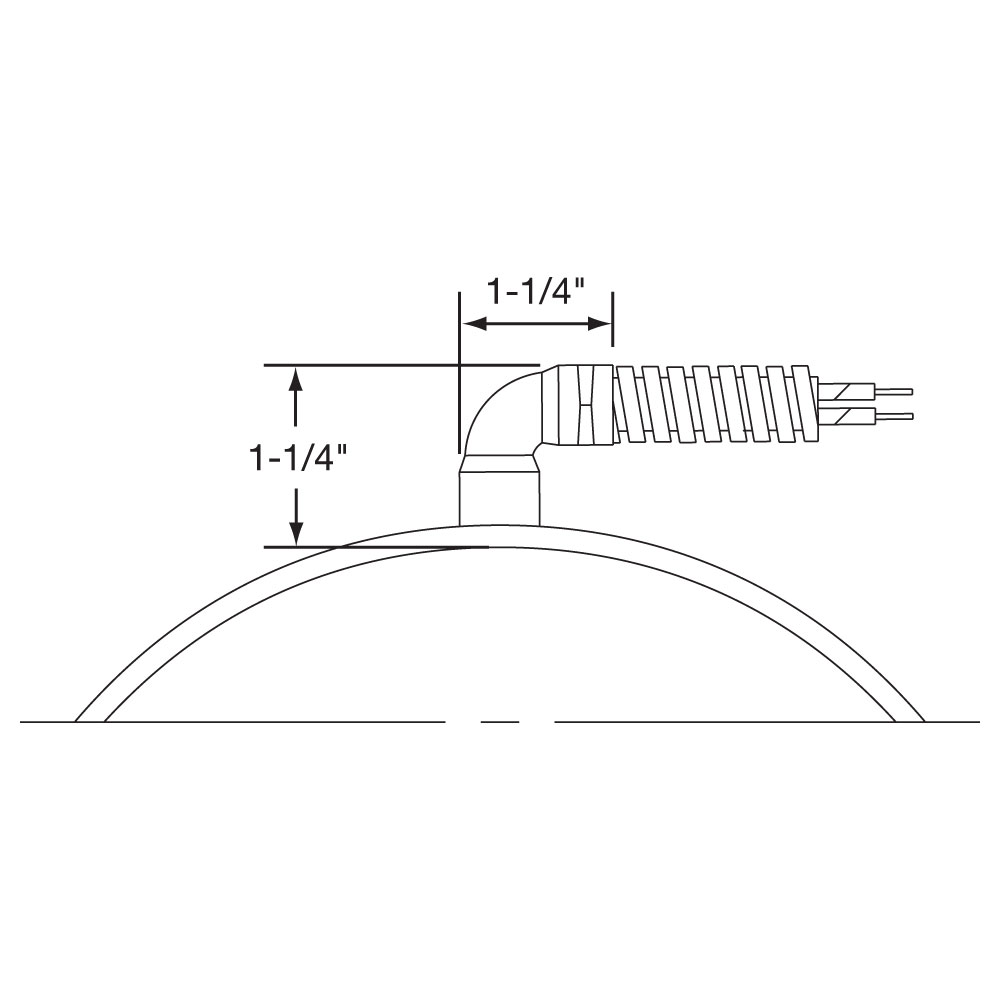
Type W2M: Right-Angle Wire Braid Leads, 90° to Heater, One-Piece Band
Standard Termination Location: opposite of gap; center of width
Minimum Inside Diameter: 1-1/2″ (38.1 mm)
Minimum Width: 1-1/4″ (31.8 mm)
Maximum Volts: 480VAC
Maximum Amps: 12.5A
Available on any clamping or construction variation. Wire braid leads offer sharp bending not possible with armor cable.
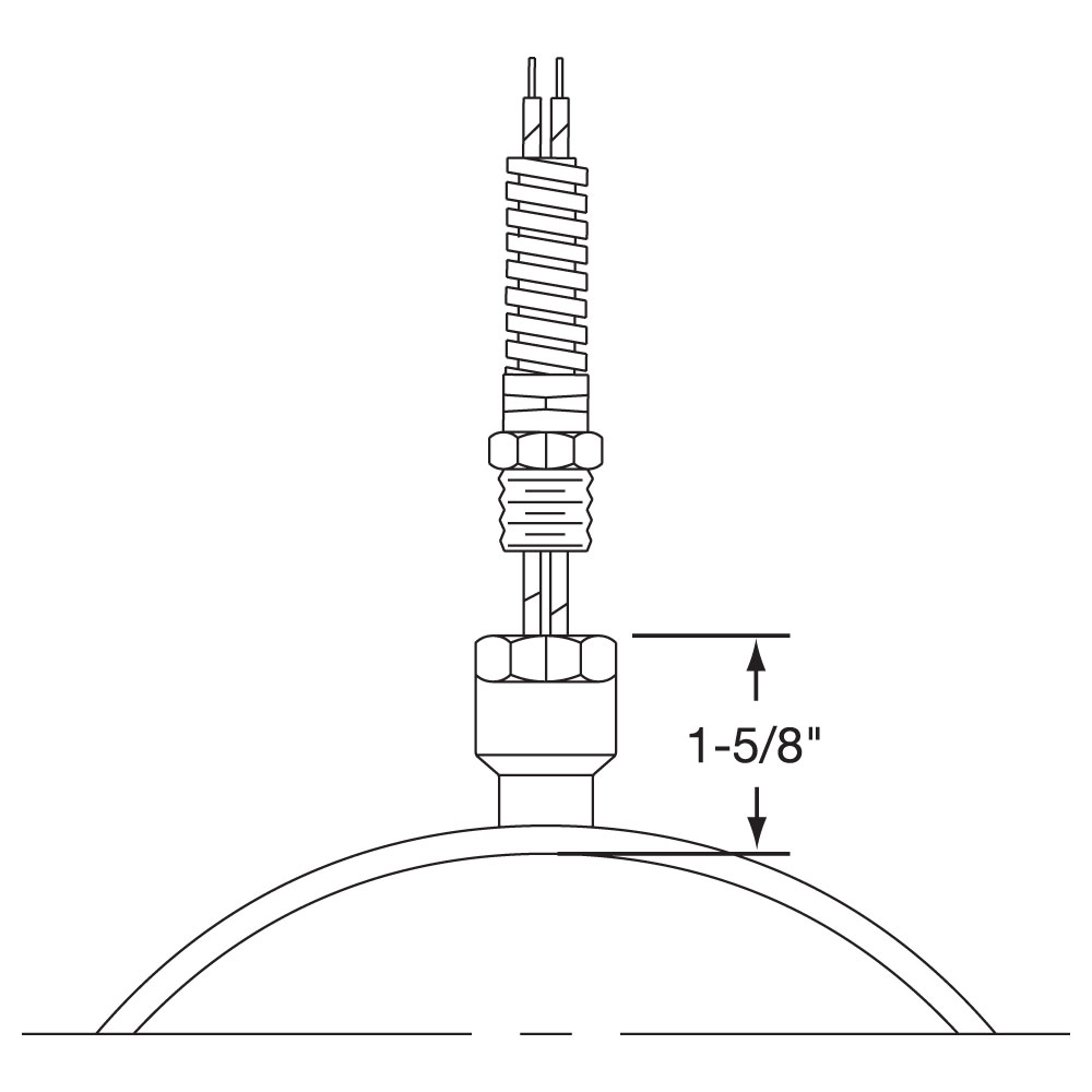
Stainless Steel Wire Braid exits perpendicular to the heater centerline through a low profile stainless steel cap. This cap acts as a strain relief which protects against excessive flexing or pulling of the lead wire. The standard leads are 10″ of wire braid over 12″ of flexible leads.
Type W2M: Right-Angle Wire Braid Leads, 90° to Heater, Two-Piece Band
Standard Termination Location: next to same gap on each half; center of width
Type W2M: Right-Angle Wire Braid Leads, 90° to Heater, Two-Piece Band
Standard Termination Location: next to same gap on each half; center of width
Minimum Inside Diameter: 2″ (50.8 mm)
Minimum Width: 1-1/4″ (31.8 mm)
Maximum Volts: 480VAC each half
Maximum Amps: 12.5A each half
Available on any clamping or construction variation. Wire braid leads offer sharp bending not possible with armor cable.
Stainless Steel Wire Braid exits perpendicular to the heater centerline through a low profile stainless steel cap. This cap acts as a strain relief which protects against excessive flexing or pulling of the lead wire. The standard leads are 10″ of wire braid over 12″ of flexible leads.
Type W2M: Right-Angle Wire Braid Leads, 90° to Heater, One-Piece Expandable Band
Standard Termination Location: next to gap; center of width
Type W2M: Right-Angle Wire Braid Leads, 90° to Heater, One-Piece Expandable Band
Standard Termination Location: next to gap; center of width
Minimum Inside Diameter: 2-1/2″ (63.5 mm)
Minimum Width: 1-1/4″ (31.8 mm)
Maximum Volts: 480VAC
Maximum Amps: 12.5A
Available on any clamping or construction variation. Wire braid leads offer sharp bending not possible with armor cable.
Stainless Steel Wire Braid exits perpendicular to the heater centerline through a low profile stainless steel cap. This cap acts as a strain relief which protects against excessive flexing or pulling of the lead wire. The standard leads are 10″ of wire braid over 12″ of flexible leads.
Type W5M: Right-Angle Wire Braid Leads, Parallel to Heater, One-Piece Band
Standard Termination Location: opposite of gap; center of width
Type W5M: Right-Angle Wire Braid Leads, Parallel to Heater, One-Piece Band
Standard Termination Location: opposite of gap; center of width
Minimum Inside Diameter: 1-1/2″ (38.1 mm)
Minimum Width: 1-1/4″ (31.8 mm)
Maximum Volts: 480VAC
Maximum Amps: 12.5A
Available on any clamping or construction variation. Wire braid leads offer sharp bending not possible with armor cable.
Stainless Steel Wire Braid exits parallel to the heater centerline through a low profile stainless steel cap. This cap acts as a strain relief which protects against excessive flexing or pulling of the lead wire. The standard leads are 10″ of wire braid over 12″ of flexible leads.
Type W5M: Right-Angle Wire Braid Leads, Parallel to Heater, Two-Piece Band
Standard Termination Location: next to same gap on each side; center of width
Type W5M: Right-Angle Wire Braid Leads, Parallel to Heater, Two-Piece Band
Standard Termination Location: next to same gap on each side; center of width
Minimum Inside Diameter: 2″ (50.8 mm)
Minimum Width: 1-1/4″ (31.8 mm)
Maximum Volts: 480VAC each half
Maximum Amps: 12.5A each half
Available on any clamping or construction variation. Wire braid leads offer sharp bending not possible with armor cable.
Stainless Steel Wire Braid exits parallel to the heater centerline through a low profile stainless steel cap. This cap acts as a strain relief which protects against excessive flexing or pulling of the lead wire. The standard leads are 10″ of wire braid over 12″ of flexible leads.
Note: The minimum heater width with a coupling is 1-1/2″. If heater width is smaller than 1-1/2″, heater gap will be used for coupling location.
Type W5M: Right-Angle Wire Braid Leads, Parallel to Heater, One-Piece Expandable Band
Standard Termination Location: next to gap; center of width
Type W5M: Right-Angle Wire Braid Leads, Parallel to Heater, One-Piece Expandable Band
Standard Termination Location: next to gap; center of width
Minimum Inside Diameter: 2-1/2″ (63.5 mm)
Minimum Width: 1-1/4″ (31.8 mm)
Maximum Volts: 480VAC
Maximum Amps: 12.5A
Available on any clamping or construction variation. Wire braid leads offer sharp bending not possible with armor cable.
Stainless Steel Wire Braid exits parallel to the heater centerline through a low profile stainless steel cap. This cap acts as a strain relief which protects against excessive flexing or pulling of the lead wire. The standard leads are 10″ of wire braid over 12″ of flexible leads.
Type R1: Straight Armor Cable, One-Piece Band
Standard Termination Location: next to gap; center of width
Standard Termination Location: next to gap; center of width
Minimum Inside Diameter: 1-1/2″ (38.1 mm)
Minimum Width: 1″ (25.4 mm)
Maximum Volts: 480VAC
Maximum Amps: 12.5A
Available on any clamping or construction variation. Armor cable provides far superior protection to lead wires where abrasion is a constant problem. The standard leads are 10″ of armor cable over 12″ of flexible leads.
R1A – Galvanized armor cable crimped in place for heaters under 2-1/2″ I.D. and/or under 1-1/4″ width. R1AT – Galvanized armor cable attached with a threaded fitting for heaters with 2-1/2″ and over I.D. and 1-1/4″ and over width. R1B – Stainless Steel armor cable crimped in place for heaters under 2-1/2″ I.D. and/or under 1-1/4″ width R1BT – Stainless Steel armor cable attached with a threaded fitting for heaters with 2-1/2″ and over I.D. and 1-1/4″ and over width. R1C – Galvanized armor cable, tack welded R1D – SS armor cable, tack welded R1E – Galvanized armor cable, full silver brazing R1F – SS armor cable, full silver brazing
Type R1: Straight Armor Cable, Two-Piece Band
Standard Termination Location: next to same gap on each half; center of width
Standard Termination Location: next to same gap on each half; center of width
Minimum Inside Diameter: 2″ (50.8 mm)
Minimum Width: 1″ (25.4 mm)
Maximum Volts/Amps: 480VAC/12.5A each half
Available on any clamping or construction variation. Armor cable provides far superior protection to lead wires where abrasion is a constant problem. The standard leads are 10″ of armor cable over 12″ of flexible leads.
R1A – Galvanized armor cable crimped in place for heaters under 2-1/2″ I.D. and/or under 1-1/4″ width.
R1AT – Galvanized armor cable attached with a threaded fitting for heaters with 2-1/2″ and over I.D. and 1-1/4″ and over width.
R1B – Stainless Steel armor cable crimped in place for heaters under 2-1/2″ I.D. and/or under 1-1/4″ width=
R1BT – Stainless Steel armor cable attached with a threaded fitting for heaters with 2-1/2″ and over I.D. and 1-1/4″ and over width.
R1C – Galvanized armor cable, tack welded
R1D – SS armor cable, tack welded
R1E – Galvanized armor cable, full silver brazing
R1F – SS armor cable, full silver brazing
Type R1: Straight Armor Cable, One-Piece Expandable Band
Standard Termination Location: next to gap; center of width
Type R1: Straight Armor Cable, One-Piece Expandable Band
Standard Termination Location: next to gap; center of width
Minimum Inside Diameter: 2-1/2″ (65.3 mm)
Minimum Width: 1-1/4″ (31.8 mm)
Maximum Volts/Amps: 480VAC/12.5A
Available on any clamping or construction variation. Armor cable provides far superior protection to lead wires where abrasion is a constant problem. The standard leads are 10″ of armor cable over 12″ of flexible leads.
R1A – Galvanized armor cable crimped in place for heaters under 2-1/2″ I.D. and/or under 1-1/4″ width. R1AT – Galvanized armor cable attached with a threaded fitting for heaters with 2-1/2″ and over I.D. and 1-1/4″ and over width. R1B – Stainless Steel armor cable crimped in place for heaters under 2-1/2″ I.D. and/or under 1-1/4″ width R1BT – Stainless Steel armor cable attached with a threaded fitting for heaters with 2-1/2″ and over I.D. and 1-1/4″ and over width. R1C – Galvanized armor cable, tack welded R1D – SS armor cable, tack welded R1E – Galvanized armor cable, full silver brazing R1F – SS armor cable, full silver brazing
Type R2: Right-Angle Armor Cable, One-Piece Band
Standard Termination Location: next to gap; center of width
Standard Termination Location: next to gap; center of width
Minimum Inside Diameter: 1-1/2″ (38.1 mm)
Minimum Width: 1-1/4″ (31.8 mm)
Maximum Volts: 480VAC
Maximum Amps: 12.5A
Available on any clamping or construction variation. Armor cable provides far superior protection to lead wires where abrasion is a constant problem. The standard leads are 10″ of armor cable over 12″ of flexible leads.
Type R2A – Galvanized armor cable, crimped Type R2B – SS armor cable, crimped Type R2C – Plain leads, no cable
Type R2: Right-Angle Armor Cable, Two-Piece Band
Standard Termination Location: next to same gap on each half; center of width
Standard Termination Location: next to same gap on each half; center of width
Minimum Inside Diameter: 2″ (50.8 mm)
Minimum Width: 1-1/4″ (31.8 mm)
Maximum Volts/Amps: 480VAC/12.5A each half
Available on any clamping or construction variation. Armor cable provides far superior protection to lead wires where abrasion is a constant problem. The standard leads are 10″ of armor cable over 12″ of flexible leads.
Type R2A – Galvanized armor cable, crimped Type R2B – SS armor cable, crimped Type R2C – Plain leads, no cable
Type R2: Right-Angle Armor Cable, One-Piece Expandable Band
Standard Termination Location: next to gap; center of width
Type R2: Right-Angle Armor Cable, One-Piece Expandable Band
Standard Termination Location: next to gap; center of width
Minimum Inside Diameter: 2-1/2″ (63.5 mm)
Minimum Width: 1-1/4″ (31.8 mm)
Maximum Volts/Amps: 480VAC/12.5A
Available on any clamping or construction variation. Armor cable provides far superior protection to lead wires where abrasion is a constant problem. The standard leads are 10″ of armor cable over 12″ of flexible leads.
Type R2A – Galvanized armor cable, crimped Type R2B – SS armor cable, crimped Type R2C – Plain leads, no cable
Type R3: Removable Armor Cable, One-Piece Band
Standard Termination Location: next to gap; center of width
Standard Termination Location: next to gap; center of width
Minimum Inside Diameter: 1-1/2″ (38.1 mm)
Minimum Width: 1-1/4″ (31.7 mm)
Maximum Volts/Amps: 480VAC/12.5A
Available on any clamping or construction variation. Armor cable provides far superior protection to lead wires where abrasion is a constant problem. The standard leads are 10″ of armor cable over 12″ of flexible leads.
Type R3A – Plain Leads & Female Fitting
Type R3B – Leads, Male Adapter & Galvanized Armor
Type R3C – Leads, Male Adapter & SS Armor
Multiple segment designs are recommended on larger diameter (typically larger than 15″) heaters to improve the clamping force and increase the surface contact between the heater and the barrel for efficient heat transfer.
Type R3: Removable Armor Cable, Two-Piece Band
Standard Termination Location: next to same gap on each half; center of width
Standard Termination Location: next to same gap on each half; center of width
Minimum Inside Diameter: 2″ (50.8 mm)
Minimum Width: 1-1/4″ (31.7 mm)
Maximum Volts/Amps: 480VAC/12.5A each half
Available on any clamping or construction variation. Armor cable provides far superior protection to lead wires where abrasion is a constant problem. The standard leads are 10″ of armor cable over 12″ of flexible leads.
Type R3A – Plain Leads & Female Fitting
Type R3B – Leads, Male Adapter & Galvanized Armor
Type R3C – Leads, Male Adapter & SS Armor
The One-Piece Expandable Band should not be opened and closed more than twice.
Type R3: Removable Armor Cable, One-Piece Expandable Band
Standard Termination Location: next to gap; center of width
Type R3: Removable Armor Cable, One-Piece Expandable Band
Standard Termination Location: next to gap; center of width
Minimum Inside Diameter: 2-1/2″ (63.5 mm)
Minimum Width: 1-1/4″ (31.8 mm)
Maximum Volts/Amps: 480VAC/12.5A
Available on any clamping or construction variation. Armor cable provides far superior protection to lead wires where abrasion is a constant problem. The standard leads are 10″ of armor cable over 12″ of flexible leads.
Type R3A – Plain Leads & Female Fitting
Type R3B – Leads, Male Adapter & Galvanized Armor
Type R3C – Leads, Male Adapter & SS Armor
Type S1: Lead Wire Spring Strain Relief, One-Piece Band
Standard Termination Location: next to gap; center of width
Type S1: Lead Wire Spring Strain Relief, One-Piece Band
Standard Termination Location: next to gap; center of width
Minimum Inside Diameter: 2″ (50.8 mm)
Minimum Width: 1-1/4″ (31.8 mm)
Maximum Volts: 480VAC
Maximum Amps: 12.5A
A strain relief spring is attached to the heater at the termination exit to reduce strain on leads subjected to excessive flexing. The spring is 2-1/8″ long. The flexible standard leads are 10″ long with 3″ of fiberglass sleeving.
Type S1A – Plain Leads and Strain Relief Spring crimped in place for heaters under 2-1/2″ I.D. and/or under 1-1/4″ width. Type S1AT – Plain Leads and Strain Relief Spring attached with a threaded fitting for heaters over/equal 2-1/2″ I.D. and over/equal 1-1/4″ width. Type S1B – Stainless Steel Wire Braided Leads and Strain Relief Spring crimped in place for heaters under 2-1/2″ I.D. and/or under 1-1/4″ width 10″ of braid over 12″ of flexible leads is standard. Type S1BT – Stainless Steel Wire Braided Leads and Strain Relief Spring attached with a threaded fitting for heaters over/equal 2-1/2″ I.D. and over/equal 1-1/4″ width. 10″ of braid over 12″ of flexible leads is standard.
Type S1: Lead Wire Spring Strain Relief, Two-Piece Band
Standard Termination Location: next to same gap on each half; center of width
Type S1: Lead Wire Spring Strain Relief, Two-Piece Band
Standard Termination Location: next to same gap on each half; center of width
Minimum Inside Diameter: 2″ (50.8 mm)
Minimum Width: 1-1/4″ (31.75 mm)
Maximum Volts/Amps: 480VAC/12.5A each half:
A strain relief spring is attached to the heater at the termination exit to reduce strain on leads subjected to excessive flexing. The spring is 2-1/8″ long. The flexible standard leads are 10″ long with 3″ of fiberglass sleeving.
Type S1A – Plain Leads and Strain Relief Spring crimped in place for heaters under 2-1/2″ I.D. and/or under 1-1/4″ width. Type S1AT – Plain Leads and Strain Relief Spring attached with a threaded fitting for heaters over/equal 2-1/2″ I.D. and over/equal 1-1/4″ width. Type S1B – Stainless Steel Wire Braided Leads and Strain Relief Spring crimped in place for heaters under 2-1/2″ I.D. and/or under 1-1/4″ width 10″ of braid over 12″ of flexible leads is standard. Type S1BT – Stainless Steel Wire Braided Leads and Strain Relief Spring attached with a threaded fitting for heaters over/equal 2-1/2″ I.D. and over/equal 1-1/4″ width. 10″ of braid over 12″ of flexible leads is standard.
Type S1: Lead Wire Spring Strain Relief, One-Piece Expandable Band
Standard Termination Location: next to gap; center of width
Type S1: Lead Wire Spring Strain Relief, One-Piece Expandable Band
Standard Termination Location: next to gap; center of width
Minimum Inside Diameter: 2-1/2″ (63.5 mm)
Minimum Width: 1-1/4″ (31.75 mm)
Maximum Volts/Amps: 480VAC/12.5A
A strain relief spring is attached to the heater at the termination exit to reduce strain on leads subjected to excessive flexing. The spring is 2-1/8″ long. The flexible standard leads are 10″ long with 3″ of fiberglass sleeving.
Type S1A – Plain Leads and Strain Relief Spring crimped in place for heaters under 2-1/2″ I.D. and/or under 1-1/4″ width. Type S1AT – Plain Leads and Strain Relief Spring attached with a threaded fitting for heaters over/equal 2-1/2″ I.D. and over/equal 1-1/4″ width. Type S1B – Stainless Steel Wire Braided Leads and Strain Relief Spring crimped in place for heaters under 2-1/2″ I.D. and/or under 1-1/4″ width 10″ of braid over 12″ of flexible leads is standard. Type S1BT – Stainless Steel Wire Braided Leads and Strain Relief Spring attached with a threaded fitting for heaters over/equal 2-1/2″ I.D. and over/equal 1-1/4″ width. 10″ of braid over 12″ of flexible leads is standard.
Type C2: Standard Terminal Boxes, One-Piece Band
Standard Termination Location: next to gap; center of width
Minimum Inside Diameter: 2-1/2″ (63.5 mm)
Minimum Width: 1″ (25.4 mm) Heater widths between 1″ and 2-1/2″ require a minimum ID of 5-1/2″ or greater.
Standard Termination Location: next to gap; center of width
Minimum Inside Diameter: 2-1/2″ (63.5 mm)
Minimum Width: 1″ (25.4 mm) Heater widths between 1″ and 2-1/2″ require a minimum ID of 5-1/2″ or greater.
Maximum Volts/Amps: 480VAC/25A
Available with any construction or clamping variation. They are a simple & economical way to protect employees from electric shock or prevent electric shorts that can result from exposed wiring on band heater electrical installations. The Heavy Duty Terminal Boxes have 1/2″ knockouts that will accept standard armor cable connectors. They can be field assembled on band heaters that have a center distance between terminal screws of 7/8″. Boxes can be pre-wired with galvanized armor, stainless steel armor, wire braid or plain leads. If a Low Profile Box with cable or leads is required, it is strongly recommended to order it pre-wired by the factory. The standard leads are 10″ of cable or wire braid over 12″ of flexible leads.
Type C2A – Box only Type C2B – w/galvanized armor Type C2C – w/stainless steel armor Type C2D – w/wire braid
Type C2: Standard Terminal Boxes, Two-Piece Band
Standard Termination Location: next to same gap on each half; center of width
Minimum Inside Diameter: 3″ (76.2 mm)
Minimum Width: 1″ (25.4 mm) Heater widths between 1″ and 2-1/2″ require a minimum ID of 5-1/2″ or greater.
Standard Termination Location: next to same gap on each half; center of width
Minimum Inside Diameter: 3″ (76.2 mm)
Minimum Width: 1″ (25.4 mm) Heater widths between 1″ and 2-1/2″ require a minimum ID of 5-1/2″ or greater.
Max. Volts/Amps: 480VAC/25A each half
Available with any construction or clamping variation. They are a simple & economical way to protect employees from electric shock or prevent electric shorts that can result from exposed wiring on band heater electrical installations. The Heavy Duty Terminal Boxes have 1/2″ knockouts that will accept standard armor cable connectors. They can be field assembled on band heaters that have a center distance between terminal screws of 7/8″. Boxes can be pre-wired with galvanized armor, stainless steel armor, wire braid or plain leads. If a Low Profile Box with cable or leads is required, it is strongly recommended to order it pre-wired by the factory. The standard leads are 10″ of cable or wire braid over 12″ of flexible leads.
Type C2A – Box only Type C2B – w/galvanized armor Type C2C – w/stainless steel armor Type C2D – w/wire braid
Type C2: Standard Terminal Boxes, One-Piece Expandable Band
Standard Termination Location: next to gap; center of width
Minimum Inside Diameter: 2-1/2″ (63.5 mm)
Minimum Width: 1″ (25.4 mm) Heater widths between 1″ and 2-1/2″ require a minimum ID of 5-1/2″ or greater.
Type C2: Standard Terminal Boxes, One-Piece Expandable Band
Standard Termination Location: next to gap; center of width
Minimum Inside Diameter: 2-1/2″ (63.5 mm)
Minimum Width: 1″ (25.4 mm) Heater widths between 1″ and 2-1/2″ require a minimum ID of 5-1/2″ or greater.
Maximum Volts/Amps: 480VAC/25A
Available with any construction or clamping variation. They are a simple & economical way to protect employees from electric shock or prevent electric shorts that can result from exposed wiring on band heater electrical installations. The Heavy Duty Terminal Boxes have 1/2″ knockouts that will accept standard armor cable connectors. They can be field assembled on band heaters that have a center distance between terminal screws of 7/8″. Boxes can be pre-wired with galvanized armor, stainless steel armor, wire braid or plain leads. If a Low Profile Box with cable or leads is required, it is strongly recommended to order it pre-wired by the factory. The standard leads are 10″ of cable or wire braid over 12″ of flexible leads.
Type C2A – Box only Type C2B – w/galvanized armor Type C2C – w/stainless steel armor Type C2D – w/wire braid
Type C5: Low-Profile Terminal Boxes, One-Piece Band
Standard Termination Location: next to gap; center of width
Minimum Inside Diameter: 2-1/2″ (63.5 mm)
Minimum Width: 1″ (25.4 mm) Heater widths between 1″ and 2-1/2″ require a minimum ID of 5-1/2″ or greater.
Type C5: Low-Profile Terminal Boxes, One-Piece Band
Standard Termination Location: next to gap; center of width
Minimum Inside Diameter: 2-1/2″ (63.5 mm)
Minimum Width: 1″ (25.4 mm) Heater widths between 1″ and 2-1/2″ require a minimum ID of 5-1/2″ or greater.
Maximum Volts/Amps: 480VAC/25A
Available with any construction or clamping variation. They are a simple & economical way to protect employees from electric shock or prevent electric shorts that can result from exposed wiring on band heater electrical installations. The Heavy Duty Terminal Boxes have 1/2″ knockouts that will accept standard armor cable connectors. They can be field assembled on band heaters that have a center distance between terminal screws of 7/8″. Boxes can be pre-wired with galvanized armor, stainless steel armor, wire braid or plain leads. If a Low Profile Box with cable or leads is required, it is strongly recommended to order it pre-wired by the factory. The standard leads are 10″ of cable or wire braid over 12″ of flexible leads.
Type C5A – box only Type C5B – w/galvanized armor Type C5C – w/SS armor Type C5D – w/wire braid Type C5J – w/plain leads
Type C5: Low-Profile Terminal Boxes, Two-Piece Band
Standard Termination Location: next to same gap on each half; center of width
Minimum Inside Diameter: 3″ (76.2 mm)
Minimum Width: 1″ (25.4 mm) Heater widths between 1″ and 2-1/2″ require a minimum ID of 5-1/2″ or greater.
Type C5: Low-Profile Terminal Boxes, Two-Piece Band
Standard Termination Location: next to same gap on each half; center of width
Minimum Inside Diameter: 3″ (76.2 mm)
Minimum Width: 1″ (25.4 mm) Heater widths between 1″ and 2-1/2″ require a minimum ID of 5-1/2″ or greater.
Max. Volts/Amps: 480VAC/25A each half
Available with any construction or clamping variation. They are a simple & economical way to protect employees from electric shock or prevent electric shorts that can result from exposed wiring on band heater electrical installations. The Heavy Duty Terminal Boxes have 1/2″ knockouts that will accept standard armor cable connectors. They can be field assembled on band heaters that have a center distance between terminal screws of 7/8″. Boxes can be pre-wired with galvanized armor, stainless steel armor, wire braid or plain leads. If a Low Profile Box with cable or leads is required, it is strongly recommended to order it pre-wired by the factory. The standard leads are 10″ of cable or wire braid over 12″ of flexible leads.
Type C5A – box only Type C5B – w/galvanized armor Type C5C – w/SS armor Type C5D – w/wire braid Type C5J – w/plain leads
Type C5: Low-Profile Terminal Boxes, One-Piece Expandable Band
Standard Termination Location: next to gap; center of width
Minimum Inside Diameter: 2-1/2″ (63.5 mm)
Minimum Width: 1″ (25.4 mm) Heater widths between 1″ and 2-1/2″ require a minimum ID of 5-1/2″ or greater
Type C5: Low-Profile Terminal Boxes, One-Piece Expandable Band
Standard Termination Location: next to gap; center of width
Minimum Inside Diameter: 2-1/2″ (63.5 mm)
Minimum Width: 1″ (25.4 mm) Heater widths between 1″ and 2-1/2″ require a minimum ID of 5-1/2″ or greater
Maximum Volts/Amps: 480VAC/25A
Available with any construction or clamping variation. They are a simple & economical way to protect employees from electric shock or prevent electric shorts that can result from exposed wiring on band heater electrical installations. The Heavy Duty Terminal Boxes have 1/2″ knockouts that will accept standard armor cable connectors. They can be field assembled on band heaters that have a center distance between terminal screws of 7/8″. Boxes can be pre-wired with galvanized armor, stainless steel armor, wire braid or plain leads. If a Low Profile Box with cable or leads is required, it is strongly recommended to order it pre-wired by the factory. The standard leads are 10″ of cable or wire braid over 12″ of flexible leads.
Type C5A – box only Type C5B – w/galvanized armor Type C5C – w/SS armor Type C5D – w/wire braid Type C5J – w/plain leads
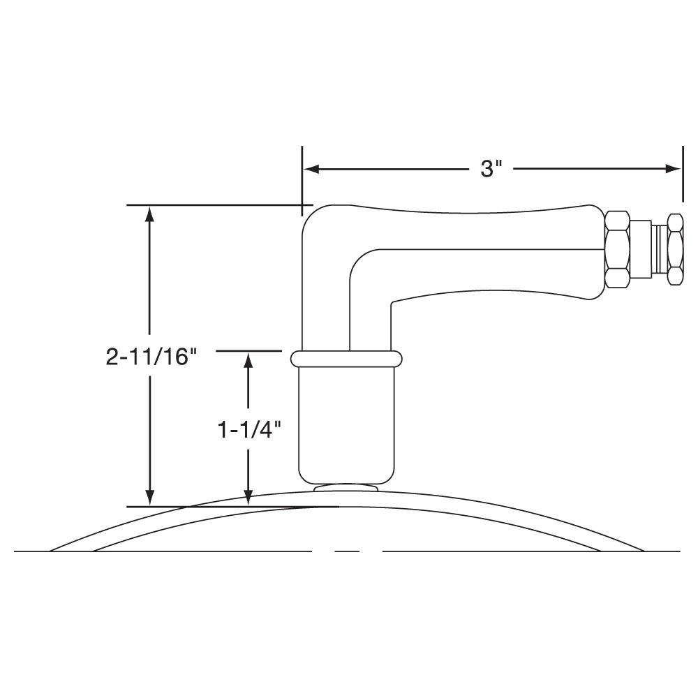
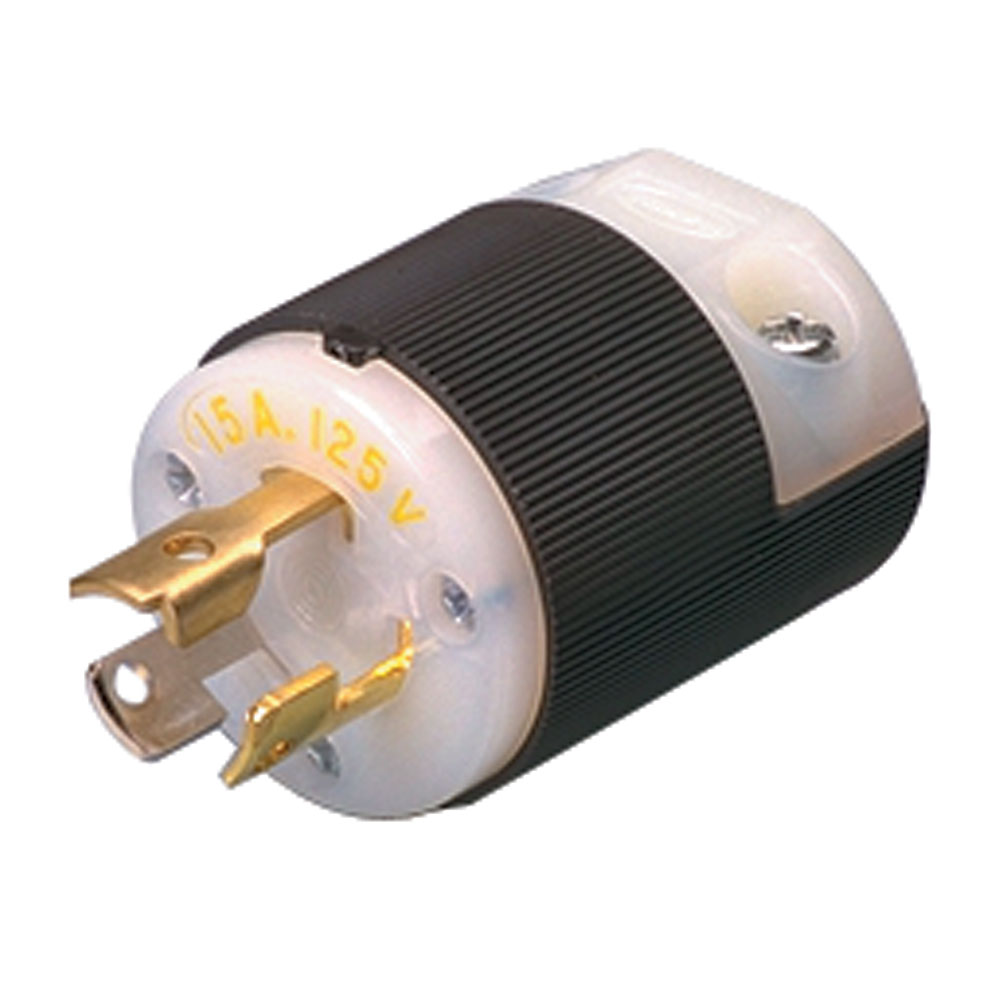
Type P1: Quick Disconnect Plugs, One-Piece Band
Standard Termination Location: next to gap; center of width
Standard Termination Location: next to gap; center of width
Minimum Inside Diameter: 2″ (50.8 mm)
Minimum Width: 1-1/2″ (38.1 mm)
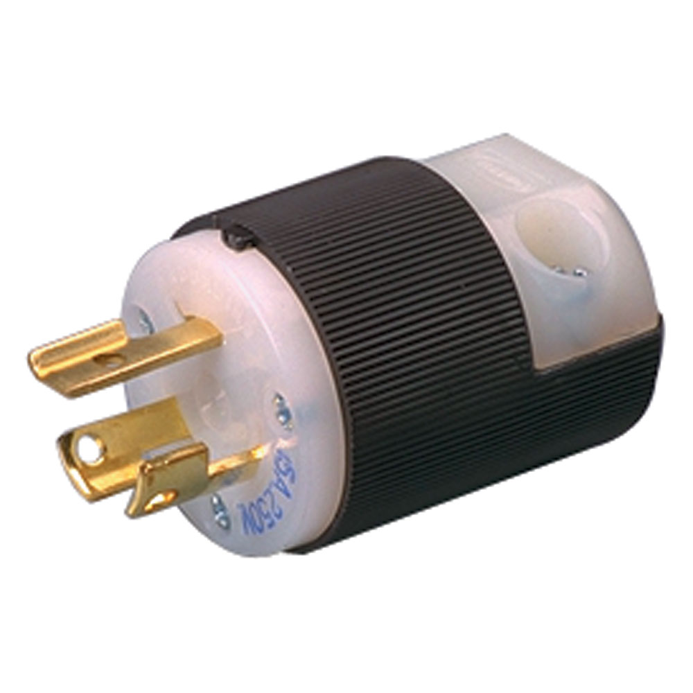
Plug Electrical Ratings: 2-Pole 3-Wire Grounding
Maximum Volts: 250 VAC
Maximum Amps: 16A
Maximum Temperature: 392°F (200°C)
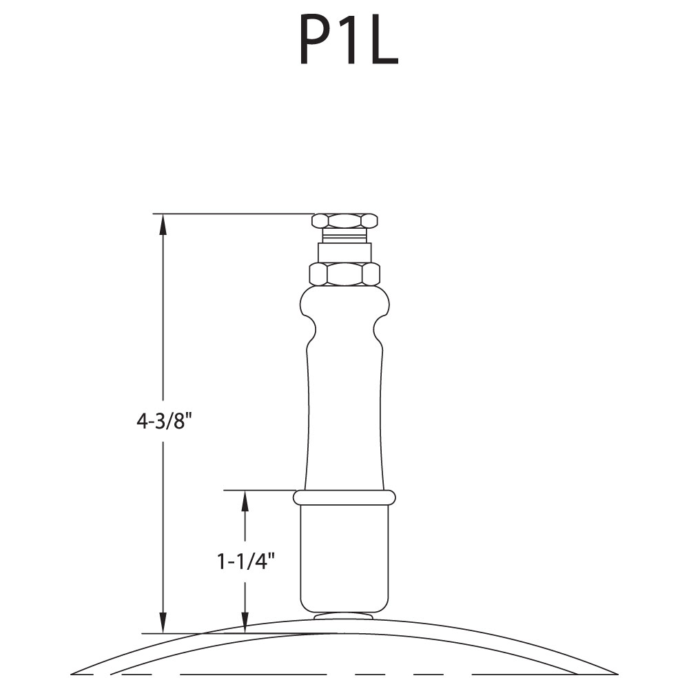
Available on any construction or clamping variation. These plug assemblies are highly recommended & should be used whenever possible. The combination of plug & cup assembly along with armor cable covered leads eliminates all live exposed terminals or wiring that can be a potential hazard to employees or machinery. Type P1 and P3 assemblies are available with a straight or right-angle plug. Type P2 and P4 plug assemblies have a lower profile and are available with a straight plug only. To simplify installation, band heaters with these assemblies can be supplied pre-wired, using high temperature lead wires. The standard leads are 10″ of armor cable over 12″ of flexible leads.
Type P1K – Cup assembly only Type P1L – w/straight plug only Type P1M – w/90° plug only Type P1N – w/str. plug & galvanized cable Type P1O – w/str. plug & SS cable Type P1P – w/str. plug & wire braid Type P1Q – w/90° plug & galvanized cable Type P1R – w/90° plug & SS cable Type P1S – w/90° plug & wire braid
If width is between 1-1/2″ and 2″, minimum diameter is 5-1/2″.
Type P1: Quick Disconnect Plugs, Two-Piece Band
Standard Termination Location: next same gap on each half; center of width
Standard Termination Location: next same gap on each half; center of width
Minimum Inside Diameter: 2″ (50.8 mm)
Minimum Width: 1-1/2″ (38.1 mm)
Plug Electrical Ratings: 2-Pole 3-Wire Grounding
Maximum Volts: 250 VAC
Maximum Amps: 16A
Maximum Temperature: 392°F (200°C)
Available on any construction or clamping variation. These plug assemblies are highly recommended & should be used whenever possible. The combination of plug & cup assembly along with armor cable covered leads eliminates all live exposed terminals or wiring that can be a potential hazard to employees or machinery. Type P1 and P3 assemblies are available with a straight or right-angle plug. Type P2 and P4 plug assemblies have a lower profile and are available with a straight plug only. To simplify installation, band heaters with these assemblies can be supplied pre-wired, using high temperature lead wires. The standard leads are 10″ of armor cable over 12″ of flexible leads.
Type P1K – Cup assembly only Type P1L – w/straight plug only Type P1M – w/90° plug only Type P1N – w/str. plug & galvanized cable Type P1O – w/str. plug & SS cable Type P1P – w/str. plug & wire braid Type P1Q – w/90° plug & galvanized cable Type P1R – w/90° plug & SS cable Type P1S – w/90° plug & wire braid
If width is between 1-1/2″ and 2″, minimum diameter is 5-1/2″.
Type P1: Quick Disconnect Plugs, One-Piece Expandable Band
Standard Termination Location: next to gap; center of width.
Type P1: Quick Disconnect Plugs, One-Piece Expandable Band
Standard Termination Location: next to gap; center of width.
Minimum Inside Diameter: 2-1/2″ (63.5 mm)
Minimum Width: 1-1/2″ (38.1 mm)
Plug Electrical Ratings: 2-Pole 3-Wire Grounding
Maximum Volts: 250 VAC
Maximum Amps: 16A
Maximum Temperature: 572°F (300°C)
Available on any construction or clamping variation. These plug assemblies are highly recommended & should be used whenever possible. The combination of plug & cup assembly along with armor cable covered leads eliminates all live exposed terminals or wiring that can be a potential hazard to employees or machinery. Type P1 and P3 assemblies are available with a straight or right-angle plug. Type P2 and P4 plug assemblies have a lower profile and are available with a straight plug only. To simplify installation, band heaters with these assemblies can be supplied pre-wired, using high temperature lead wires. The standard leads are 10″ of armor cable over 12″ of flexible leads.
Type P1K – Cup assembly only Type P1L – w/straight plug only Type P1M – w/90° plug only Type P1N – w/str. plug & galvanized cable Type P1O – w/str. plug & SS cable Type P1P – w/str. plug & wire braid Type P1Q – w/90° plug & galvanized cable Type P1R – w/90° plug & SS cable Type P1S – w/90° plug & wire braid
If width is between 1-1/2″ and 2″, minimum diameter is 5-1/2″. If width is greater than 2″, minimum diameter is 2″.
Type P2: Quick Disconnect Plugs, Low-Profile, One-Piece Band
Standard Termination Location: next to gap; center of width
Type P2: Quick Disconnect Plugs, Low-Profile, One-Piece Band
Standard Termination Location: next to gap; center of width
Minimum Inside Diameter: 3″ (76.2 mm)
Minimum Width: 2-1/2″ (63.5 mm)
Plug Electrical Ratings: 2-Pole 3-Wire Grounding
Maximum Volts: 250 VAC
Maximum Amps: 16A
Maximum Temperature: 392°F (200°C)
Available on any construction or clamping variation. These plug assemblies are highly recommended & should be used whenever possible. The combination of plug & cup assembly along with armor cable covered leads eliminates all live exposed terminals or wiring that can be a potential hazard to employees or machinery. Type P1 and P3 assemblies are available with a straight or right-angle plug. Type P2 and P4 plug assemblies have a lower profile and are available with a straight plug only. To simplify installation, band heaters with these assemblies can be supplied pre-wired, using high temperature lead wires. The standard leads are 10″ of armor cable over 12″ of flexible leads.
Type P2F – Low profile assembly only Type P2G – w/straight plug only Type P2H – w/str. plug and galvanized cable Type P2J – w/str. plug and SS cable Type P2K – w/str. plug and wire braid
Type P2: Quick Disconnect Plugs, Low-Profile, Two-Piece Band
Standard Termination Location: next same gap on each half; center of width
Type P2: Quick Disconnect Plugs, Low-Profile, Two-Piece Band
Standard Termination Location: next same gap on each half; center of width
Minimum Inside Diameter: 3″ (76.2 mm)
Minimum Width: 2-1/2″ (63.5 mm)
Plug Electrical Ratings: 2-Pole 3-Wire Grounding
Maximum Volts: 250 VAC
Maximum Amps: 16A
Maximum Temperature: 572°F (300°C)
Available on any construction or clamping variation. These plug assemblies are highly recommended & should be used whenever possible. The combination of plug & cup assembly along with armor cable covered leads eliminates all live exposed terminals or wiring that can be a potential hazard to employees or machinery. Type P1 and P3 assemblies are available with a straight or right-angle plug. Type P2 and P4 plug assemblies have a lower profile and are available with a straight plug only. To simplify installation, band heaters with these assemblies can be supplied pre-wired, using high temperature lead wires. The standard leads are 10″ of armor cable over 12″ of flexible leads.
TypeP2F – Low profile assembly only Type P2G – w/straight plug only Type P2H – w/str. plug and galvanized cable Type P2J – w/str. plug and SS cable Type P2K – w/str. plug and wire braid
Type P2: Quick Disconnect Plugs, Low-Profile, One-Piece Expandable Band
Standard Termination Location: next to gap on each half; center of width
Type P2: Quick Disconnect Plugs, Low-Profile, One-Piece Expandable Band
Standard Termination Location: next to gap on each half; center of width
Minimum Inside Diameter: 3″ (76.2 mm)
Minimum Width: 2-1/2″ (63.5 mm)
Plug Electrical Ratings: 2-Pole 3-Wire Grounding
Maximum Volts: 250 VAC
Maximum Amps: 16A
Maximum Temperature: 572°F (300°C)
Available on any construction or clamping variation. These plug assemblies are highly recommended & should be used whenever possible. The combination of plug & cup assembly along with armor cable covered leads eliminates all live exposed terminals or wiring that can be a potential hazard to employees or machinery. Type P1 and P3 assemblies are available with a straight or right-angle plug. Type P2 and P4 plug assemblies have a lower profile and are available with a straight plug only. To simplify installation, band heaters with these assemblies can be supplied pre-wired, using high temperature lead wires. The standard leads are 10″ of armor cable over 12″ of flexible leads.
Type P2F – Low profile assembly only
Type P2G – w/straight plug only
Type P2H – w/str. plug and galvanized cable
Type P2J – w/str. plug and SS cable
Type P2K – w/str. plug and wire braid
Type P3: DIN 49458 A/B Quick Disconnect Plugs, Vertical, One-Piece Band
Standard Termination Location: next to gap; center of width
Type P3: DIN 49458 A/B Quick Disconnect Plugs, Vertical, One-Piece Band
Standard Termination Location: next to gap; center of width
Minimum Inside Diameter: 3″ (76.2 mm)
Minimum Width: 2-1/2″ (63.5 mm)
Plug Electrical Ratings: 2-Pole 3-Wire Grounding
Maximum Volts: 250 VAC
Maximum Amps: 16A
Maximum Temperature: 392°F (200°C)
Available on any construction or clamping variation. These plug assemblies are highly recommended & should be used whenever possible. The combination of plug & cup assembly along with armor cable covered leads eliminates all live exposed terminals or wiring that can be a potential hazard to employees or machinery. Type P1 and P3 assemblies are available with a straight or right-angle plug. Type P2 and P4 plug assemblies have a lower profile and are available with a straight plug only. To simplify installation, band heaters with these assemblies can be supplied pre-wired, using high temperature lead wires. The standard leads are 10″ of armor cable over 12″ of flexible leads.
Type P3A – Box assembly only Type P3B – Box assembly w/straight plug Type P3C – Box assembly w/right-angle plug only
Type P3: DIN 49458 A/B Quick Disconnect Plugs, Vertical, Two-Piece Band
Standard Termination Location: next to same gap on each half; center of width
Type P3: DIN 49458 A/B Quick Disconnect Plugs, Vertical, Two-Piece Band
Standard Termination Location: next to same gap on each half; center of width
Minimum Inside Diameter: 3″ (76.2 mm)
Minimum Width: 2-1/2″ (63.5 mm)
Plug Electrical Ratings: 2-Pole 3-Wire Grounding
Maximum Volts: 250 VAC
Maximum Amps: 16A
Maximum Temperature: 392°F (200°C)
Available on any construction or clamping variation. These plug assemblies are highly recommended & should be used whenever possible. The combination of plug & cup assembly along with armor cable covered leads eliminates all live exposed terminals or wiring that can be a potential hazard to employees or machinery. Type P1 and P3 assemblies are available with a straight or right-angle plug. Type P2 and P4 plug assemblies have a lower profile and are available with a straight plug only. To simplify installation, band heaters with these assemblies can be supplied pre-wired, using high temperature lead wires. The standard leads are 10″ of armor cable over 12″ of flexible leads.
Type P3A – Box assembly only Type P3B – Box assembly w/straight plug Type P3C – Box assembly w/right-angle plug only
Type P3: DIN 49458 A/B Quick Disconnect Plugs, Vertical, One-Piece Expandable Band
Standard Termination Location: next to same gap on each half; center of width
Type P3: DIN 49458 A/B Quick Disconnect Plugs, Vertical, One-Piece Expandable Band
Standard Termination Location: next to same gap on each half; center of width
Minimum Inside Diameter: 3″ (76.2 mm)
Minimum Width: 2-1/2″ (63.5 mm)
Plug Electrical Ratings: 2-Pole 3-Wire Grounding
Maximum Volts: 250 VAC
Maximum Amps: 16A
Maximum Temperature: 392°F (200°C)
Available on any construction or clamping variation. These plug assemblies are highly recommended & should be used whenever possible. The combination of plug & cup assembly along with armor cable covered leads eliminates all live exposed terminals or wiring that can be a potential hazard to employees or machinery. Type P1 and P3 assemblies are available with a straight or right-angle plug. Type P2 and P4 plug assemblies have a lower profile and are available with a straight plug only. To simplify installation, band heaters with these assemblies can be supplied pre-wired, using high temperature lead wires. The standard leads are 10″ of armor cable over 12″ of flexible leads.
Type P3A – Box assembly only Type P3B – Box assembly w/straight plug Type P3C – Box assembly w/right-angle plug only
Type P4: DIN 49458 A/B Quick Disconnect Plugs, Horizontal, One-Piece Band
Standard Termination Location: next to gap; center of width
Type P4: DIN 49458 A/B Quick Disconnect Plugs, Horizontal, One-Piece Band
Standard Termination Location: next to gap; center of width
Minimum Inside Diameter: 3″ (76.2 mm)
Minimum Width: 2-1/2″ (63.5 mm)
Plug Electrical Ratings: 2-Pole 3-Wire Grounding
Maximum Volts: 250 VAC
Maximum Amps: 16A
Maximum Temperature: 392°F (200°C)
Available on any construction or clamping variation. These plug assemblies are highly recommended & should be used whenever possible. The combination of plug & cup assembly along with armor cable covered leads eliminates all live exposed terminals or wiring that can be a potential hazard to employees or machinery. Type P1 and P3 assemblies are available with a straight or right-angle plug. Type P2 and P4 plug assemblies have a lower profile and are available with a straight plug only. To simplify installation, band heaters with these assemblies can be supplied pre-wired, using high temperature lead wires. The standard leads are 10″ of armor cable over 12″ of flexible leads.
Type P4A – Box assembly only Type P4B – Box assembly with straight plug
Type P4: DIN 49458 A/B Quick Disconnect Plugs, Horizontal, Two-Piece Band
Standard Termination Location: next to same gap on each half; center of width
Type P4: DIN 49458 A/B Quick Disconnect Plugs, Horizontal, Two-Piece Band
Standard Termination Location: next to same gap on each half; center of width
Minimum Inside Diameter: 3″ (76.2 mm)
Minimum Width: 2-1/2″ (63.5 mm)
Plug Electrical Ratings: 2-Pole 3-Wire Grounding
Maximum Volts: 250 VAC
Maximum Amps: 16A
Maximum Temperature: 392°F (200°C)
Available on any construction or clamping variation. These plug assemblies are highly recommended & should be used whenever possible. The combination of plug & cup assembly along with armor cable covered leads eliminates all live exposed terminals or wiring that can be a potential hazard to employees or machinery. Type P1 and P3 assemblies are available with a straight or right-angle plug. Type P2 and P4 plug assemblies have a lower profile and are available with a straight plug only. To simplify installation, band heaters with these assemblies can be supplied pre-wired, using high temperature lead wires. The standard leads are 10″ of armor cable over 12″ of flexible leads.
Type P4A – Box assembly only Type P4B – Box assembly with straight plug
Type P4: DIN 49458 A/B Quick Disconnect Plugs, Horizontal, One-Piece Expandable Band
Standard Termination Location: next to gap; center of width
Type P4: DIN 49458 A/B Quick Disconnect Plugs, Horizontal, One-Piece Expandable Band
Standard Termination Location: next to gap; center of width
Minimum Inside Diameter: 3″ (76.2 mm)
Minimum Width: 2-1/2″ (63.5 mm)
Plug Electrical Ratings: 2-Pole 3-Wire Grounding
Maximum Volts: 250 VAC
Maximum Amps: 16A
Maximum Temperature: 392°F (200°C)
Available on any construction or clamping variation. These plug assemblies are highly recommended & should be used whenever possible. The combination of plug & cup assembly along with armor cable covered leads eliminates all live exposed terminals or wiring that can be a potential hazard to employees or machinery. Type P1 and P3 assemblies are available with a straight or right-angle plug. Type P2 and P4 plug assemblies have a lower profile and are available with a straight plug only. To simplify installation, band heaters with these assemblies can be supplied pre-wired, using high temperature lead wires. The standard leads are 10″ of armor cable over 12″ of flexible leads.
Type P4A – Box assembly only Type P4B – Box assembly with straight plug
Additional Options
No options available for this section based on your selections
Igloo® Ceramic Terminal Covers
Igloo® Ceramic Terminal Covers consist of two individual ceramic parts. Unlike conventional ceramic caps, Igloo fully insulates any standard #8 or #10 terminal lugs used for electrical hook-ups.
Limitations Minimum Inside Diamter: 2″ (50.8 mm)
Minimum Width: 1-1/4″ (31.7 mm) To assemble Igloo covers, termainsl should be at least 7/8″ apart.
Three types of Igloo™ bases are available: Type C6 – Double Port In-Line P/N CER-101-104 Type C7 – Double Port 90° P/N CER-101-106 Type C8 – Single Port P/N CER-101-107
Igloo™caps are available in the following three screw terminal sizes: 10-32 – P/N CER-102-101 10-24 – P/N CER-102-104 8-32 – P/N CER-102-105
When ordering, specify the type of Igloo and the screw terminal size.
Thermocouple Bayonet Adapter
A standard Bayonet Adapter facilitates the installation of an external thermocouple with a standard bayonet cap. The standard location for the adapter is 90° from the gap. Specify without through hole for heater sensing or with through hole for load sensing. For heaters less than 1″ wide order separate strap clamping and utilize the gap for the thermocouple. Refer to Temperature Sensors for a complete selection of thermocouples available from stock.
A standard Bayonet Adapter facilitates the installation of an external thermocouple with a standard bayonet cap. The standard location for the adapter is 90° from the gap. Specify without through hole for heater sensing or with through hole for load sensing. For heaters less than 1″ wide order separate strap clamping and utilize the gap for the thermocouple. Refer to Temperature Sensors for a complete selection of thermocouples available from stock.
Thermocouple Bayonet Adapter
Thermocouple Coupling
The Thermocouple Coupling facilitates the installation of an external thermocouple with a threaded fitting to sense the temperature of the band. The standard location for the coupling is 90° from the gap. Specify without through hole for heater sensing or with through hole for load sensing.
The Thermocouple Coupling facilitates the installation of an external thermocouple with a threaded fitting to sense the temperature of the band. The standard location for the coupling is 90° from the gap. Specify without through hole for heater sensing or with through hole for load sensing.
Thread
D
H
1/8-27 NPT
9/16″
5/8″
1/4-18 NPT
3/4″
11/16″
3/8-18 NPT
7/8″
5/8″
M12–1.75 mm
3/4″
1/2″
Scroll for more
Holes and Cutouts
Holes and cutouts are normally required in band heaters for clearance for thermocouple probes or holding bolts. An oversize gap can in many cases serve the same purpose, saving the expense of the hole. Using the center of the gap as a starting point, specify the location of the centerpoint of the hole or cutout in terms of degrees and the distance from the edge of the heater. In addition, state the size of the hole or cutout. For critical hole and cutout locations, a detailed drawing will be required.
Holes and cutouts are normally required in band heaters for clearance for thermocouple probes or holding bolts. An oversize gap can in many cases serve the same purpose, saving the expense of the hole. Using the center of the gap as a starting point, specify the location of the centerpoint of the hole or cutout in terms of degrees and the distance from the edge of the heater. In addition, state the size of the hole or cutout. For critical hole and cutout locations, a detailed drawing will be required.
Hinged Two-Piece Band
The Hinged Two-Piece Band Heater is connected with a continuous hinge for easy installation and removal. This heater can be opened and closed as often as is necessary. The preferred method of clamping is latch and trunnion. It is available with any screw or lead variation. When ordering, specify watts and volts each half. Minimum Width: 1-3/8″ (34.9 mm)
The Hinged Two-Piece Band Heater is connected with a continuous hinge for easy installation and removal. This heater can be opened and closed as often as is necessary. The preferred method of clamping is latch and trunnion. It is available with any screw or lead variation. When ordering, specify watts and volts each half. Minimum Width: 1-3/8″ (34.9 mm)
Ring Heaters
When ordering Ring Heaters, specify inside and outside diameters. If mounting holes are required, specify location and hole size. For critical hole and cutout locations, a detailed drawing will be required.
When ordering Ring Heaters, specify inside and outside diameters. If mounting holes are required, specify location and hole size. For critical hole and cutout locations, a detailed drawing will be required.
Ring Heaters
Cone Shapes
Cone Shaped Heaters are normally used for special heating applications when heat is required for hoppers or funnels. They are made strictly to customer specifications. The preferred method of attachment is with built-in bracket clamping. When ordering or for quoting purposes, supply a detailed drawing or sample part. Include the top ID, bottom ID, and the vertical rise or heater width.
Cone Shaped Heaters are normally used for special heating applications when heat is required for hoppers or funnels. They are made strictly to customer specifications. The preferred method of attachment is with built-in bracket clamping. When ordering or for quoting purposes, supply a detailed drawing or sample part. Include the top ID, bottom ID, and the vertical rise or heater width.
Cone Shapes
Special Custom Designs
No other heater band has the design and manufacturing flexibility of mica insulated heaters. Tempco’s flexible CNC sheet metal fabricating machines, custom developed engineering programs with built-in intelligence, and experienced and talented engineering staff allow us to push the limits on band heater designs. As a custom heating element manufacturer, we recognize that many applications require non-standard and unique designs. At Tempco, we are constantly challenged by our customers to solve their heating applications. When you have a special application and you want someone to work who has a “think outside the box” mentality, call Tempco.
No other heater band has the design and manufacturing flexibility of mica insulated heaters. Tempco’s flexible CNC sheet metal fabricating machines, custom developed engineering programs with built-in intelligence, and experienced and talented engineering staff allow us to push the limits on band heater designs. As a custom heating element manufacturer, we recognize that many applications require non-standard and unique designs. At Tempco, we are constantly challenged by our customers to solve their heating applications. When you have a special application and you want someone to work who has a “think outside the box” mentality, call Tempco.
📦
Three-Phase
On very high wattage band heaters it would be advantageous to set up the wiring three-phase to reduce the current load across a single conductor. Three-Phase wiring is available on select clamping/construction or termination variation (termination location is subject to engineering approval). Min. ID: 3″ (76.2 mm) Min. Width: 2″ (50.8 mm)
On very high wattage band heaters it would be advantageous to set up the wiring three-phase to reduce the current load across a single conductor. Three-Phase wiring is available on select clamping/construction or termination variation (termination location is subject to engineering approval). Min. ID: 3″ (76.2 mm) Min. Width: 2″ (50.8 mm)
📦
Dual Voltage
Band heaters can be designed using 3-wire series/parallel circuits for dual voltage applications. Whether the heater is run on the higher or lower voltage, the wattage will be the same. Dual Voltage wiring is available on any clamping/construction or termination variation.
Band heaters can be designed using 3-wire series/parallel circuits for dual voltage applications. Whether the heater is run on the higher or lower voltage, the wattage will be the same. Dual Voltage wiring is available on any clamping/construction or termination variation.
📦
Ground Terminal or Lead
For those applications requiring a separate ground terminal or lead attached to the heater sheath. A Ground Terminal or Lead is available on any clamping/construction or termination variation.
For those applications requiring a separate ground terminal or lead attached to the heater sheath. A Ground Terminal or Lead is available on any clamping/construction or termination variation.
📦
Single Phase/Three Phase
Duraband Heaters can be designed with multiple circuits to operate single or three-phase.
Duraband Heaters can be designed with multiple circuits to operate single or three-phase.
📦
Built-In Thermocouples
Heaters can be manufactured with a Built-In Thermocouple to closely control the temperature of the heater. Type J or K thermocouples are available with fiberglass, wire braid or any other required insulation.
Heaters can be manufactured with a Built-In Thermocouple to closely control the temperature of the heater. Type J or K thermocouples are available with fiberglass, wire braid or any other required insulation.
📦
All Stainless Steel Construction
All Stainless Steel Construction Mica band heaters can be constructed with the external sheath made entirely from stainless steel. This allows the Duraband to reach the maximum temperature of 1200°F (650°C). All Stainless Steel Construction is available on any clamping/construction or termination variation.
All Stainless Steel Construction Mica band heaters can be constructed with the external sheath made entirely from stainless steel. This allows the Duraband to reach the maximum temperature of 1200°F (650°C). All Stainless Steel Construction is available on any clamping/construction or termination variation.
📦
Other Sheath Materials
Other sheath materials, such as rust-resistant steel, Monel®, aluminum, or copper are also available for unique applications.
Other sheath materials, such as rust-resistant steel, Monel®, aluminum, or copper are also available for unique applications.
Electrical Plugs
Industry standard NEMA Twist-Lock® electrical plugs are available. The plugs can be attached to fiberglass leads, armor cable or wire braid. Electrical Plugs can be added to any clamping/construction or termination variation.
Industry standard NEMA Twist-Lock® electrical plugs are available. The plugs can be attached to fiberglass leads, armor cable or wire braid. Electrical Plugs can be added to any clamping/construction or termination variation.
P4 Electrical PlugP5 Electrical Plug
📦
Terminal Lugs
Various types of crimp terminals can be attached to the heater leads to make wiring into applications quick and easy. High temperature 1200°F (649°C) ring terminals and nylon or PVC insulated terminals are available. Spade, ring, and right-angle or straight quick disconnect type terminals can be attached to the leads.
Various types of crimp terminals can be attached to the heater leads to make wiring into applications quick and easy. High temperature 1200°F (649°C) ring terminals and nylon or PVC insulated terminals are available. Spade, ring, and right-angle or straight quick disconnect type terminals can be attached to the leads.
Sinuated Element
An alternative to wound ribbon core heaters is the sinuated heater element. In this type of construction, the heating element resistance wire is sinuated, or “formed” back and forth without a middle core layer of mica insulation. The heating element is then sandwiched between two layers of specially selected mica insulation to provide excellent thermal conductivity and dielectric strength. The sinuated formed element lends itself to lower temperature and watt density applications where high watt density construction is not required.
An alternative to wound ribbon core heaters is the sinuated heater element. In this type of construction, the heating element resistance wire is sinuated, or “formed” back and forth without a middle core layer of mica insulation. The heating element is then sandwiched between two layers of specially selected mica insulation to provide excellent thermal conductivity and dielectric strength. The sinuated formed element lends itself to lower temperature and watt density applications where high watt density construction is not required.
Type W4: Wire Braid Leads On One Side, One-Piece Band Standard Termination Location: next to gap; edge of width Minimum Inside Diameter: 7/8″ (22.2 mm) Minimum Width: 1″ (25.4 mm) Maximum Volts: 480VAC Maximum Amps: 12.5A Available on any clamping or construction variation. Wire braid leads offer sharp bending not possible with armor cable. A suitable termination for nozzle heating applications. The standard leads are 10″ of wire braid over 12″ of flexible leads. Electrical Terminations 1 Piece Additional Options Brackets Clamping Options Clamping Straps Construction Options Construction Styles Electrical Variations Flange Latch and Trunnion Lead Variations Temperature Sensors Terminal Covers Wedge Lock Wire Braids Type W4: Wire Braid Leads On One Side, One-Piece Expandable Band Standard Termination Location: next to gap; edge of width Minimum Inside Diameter: 2-1/2″ (63.5 mm) Minimum Width: 1-1/4″ (31.8 mm) Maximum Volts: 480VAC Maximum Amps: 12.5A 1 Piece Expandable Type W4: Wire Braid Leads On One Side, Two-Piece Band Standard Termination Location: next to same gap on each half; edge of width Minimum Inside Diameter: 2″ (50.8 mm) Minimum Width: 1″ (25.4 mm) Maximum Volts: 480VAC each half Maximum Amps: 12.5A each half Available on any clamping or construction variation. Wire braid leads offer sharp bending not possible with armor cable. A suitable termination for nozzle heating applications. The standard leads are 10″ of wire braid over 12″ of flexible leads. 2 Piece Type W5M: Right-Angle Wire Braid Leads, Parallel to Heater, One-Piece Band Standard Termination Location: opposite of gap; center of width Minimum Inside Diameter: 1-1/2″ (38.1 mm) Minimum Width: 1-1/4″ (31.8 mm) Maximum Volts: 480VAC Maximum Amps: 12.5A Available on any clamping or construction variation. Wire braid leads offer sharp bending not possible with armor cable. Stainless Steel Wire Braid exits parallel to the heater centerline through a low profile stainless steel cap. This cap acts as a strain relief which protects against excessive flexing or pulling of the lead wire. The standard leads are 10″ of wire braid over 12″ of flexible leads. Type W5M: Right-Angle Wire Braid Leads, Parallel to Heater, One-Piece Expandable Band Standard Termination Location: next to gap; center of width Minimum Inside Diameter: 2-1/2″ (63.5 mm) Minimum Width: 1-1/4″ (31.8 mm) Maximum Volts: 480VAC Maximum Amps: 12.5A Type W5M: Right-Angle Wire Braid Leads, Parallel to Heater, Two-Piece Band Standard Termination Location: next to same gap on each side; center of width Minimum Inside Diameter: 2″ (50.8 mm) Minimum Width: 1-1/4″ (31.8 mm) Maximum Volts: 480VAC each half Maximum Amps: 12.5A each half Note: The minimum heater width with a coupling is 1-1/2". If heater width is smaller than 1-1/2", heater gap will be used for coupling location. Type W2: Wire Braid Leads, One-Piece Band Standard Termination Location: opposite the gap; edge of width Minimum Inside Diameter: 7/8″ (22.2 mm) Minimum Width: 1-1/8″ (28.6 mm) Maximum Volts: 480VAC Maximum Amps: 12.5A Available on any clamping or construction variation. Wire braid leads offer sharp bending not possible with armor cable. The W2 wire braid exits at the middle of the segment on 1 and 2 piece designs and offset 1″ from the middle of the segmet for expandable designs. Sleeving is used for additional protection. The standard leads are 10″ of wire braid over 12″ of flexible leads with 3″ of fiberglass sleeving. Type W2: Wire Braid Leads, One-Piece Expandable Band Standard Termination Location: opposite the gap offset 1″; edge of width Minimum Inside Diameter: 2-1/2″ (63.5 mm) Minimum Width: 1-1/8″ (28.6 mm) Maximum Volts: 480VAC Maximum Amps: 12.5A Type W2: Wire Braid Leads, Two-Piece Band Standard Termination Location: center of each half; edge of width Minimum Inside Diameter: 2″ (50.8 mm) Minimum Width: 1-1/8″ (28.6 mm) Maximum Volts: 480VAC each half Maximum Amps: 12.5A each half Type W2M: Right-Angle Wire Braid Leads, 90° to Heater, One-Piece Band Available on any clamping or construction variation. Wire braid leads offer sharp bending not possible with armor cable. Stainless Steel Wire Braid exits perpendicular to the heater centerline through a low profile stainless steel cap. This cap acts as a strain relief which protects against excessive flexing or pulling of the lead wire. The standard leads are 10″ of wire braid over 12″ of flexible leads. Type W2M: Right-Angle Wire Braid Leads, 90° to Heater, One-Piece Expandable Band Type W2M: Right-Angle Wire Braid Leads, 90° to Heater, Two-Piece Band Standard Termination Location: next to same gap on each half; center of width Minimum Inside Diameter: 2″ (50.8 mm) Minimum Width: 1-1/4″ (31.8 mm) Maximum Volts: 480VAC each half Maximum Amps: 12.5A each half Type W3: Single Wire Braid Leads, One-Piece Band Standard Termination Location: each side of gap; edge of width Minimum Inside Diameter: 3/4″ (19.1 mm) Minimum Width: 7/8″ (22.2 mm) Maximum Volts: 480VAC Maximum Amps: 12.5A Available on any clamping or construction variation. Wire braid leads offer sharp bending not possible with armor cable. Highly recommended for nozzle heating applications. The standard leads are 10″ of wire braid over 12″ of flexible leads with 3″ of fiberglass sleeving. Type W3: Single Wire Braid Leads, One-Piece Expandable Band Standard Termination Location: each side of gap; edge of width Minimum Inside Diameter: 2-1/2″ (63.5 mm) Minimum Width: 1-1/4″ (31.8 mm) Maximum Volts: 480VAC Maximum Amps: 12.5A Type W3: Single Wire Braid Leads, Two-Piece Band Standard Termination Location: each side of each gap; edge of width Minimum Inside Diameter: 2″ (50.8 mm) Minimum Width: 3/4″ (19.1 mm) Maximum Volts: 480VAC each half Maximum Amps: 12.5A each half Type W1 & W1T: Straight Wire Braid Leads, One-Piece Band Standard Termination Location: next to gap; center of width Minimum Inside Diameter: 2″ (50.8 mm) Minimum Width: 1″ (25.4 mm) Maximum Volts: 480VAC Maximum Amps: 12.5A Available on any clamping or construction variation. Wire braid leads offer sharp bending not possible with armor cable. W1 – Braided lead wire crimped in place for heaters under 2-1/2″ I.D. and/or under 1-1/4″ width. W1T – Braided lead wire attached with a threaded fitting for heaters with 2-1/2″ and over I.D. and 1-1/4″ and over width. Type W1 & W1T:: Straight Wire Braid Leads, One-Piece Expandable Band Type W1 & W1T:: Straight Wire Braid Leads, Two-Piece Band Standard Termination Location: next to same gap on each half; center of width Minimum Inside Diameter: 2″ (50.8 mm) Minimum Width: 1″ (25.4 mm) Maximum Volts: 480VAC each half Maximum Amps: 12.5A each half Type TWL: Wedge Lock, One-Piece Band Wedge Lock clamping is designed for applications where mounting space is severely limited. It lends itself mainly to small diameter nozzle heaters. Limitations Minimum Inside Diameter: 1″ (25.4 mm) Minimum Width: 1″ (25.4 mm) Maximum Width: 3-1/2″ (88.9 mm) Armor Cable Lead Wire Quick Disconnect Plugs Screw Terminals Terminal Housings Type T3: Screw Terminals, One-Piece Band Standard Termination Location: next to gap; across center of width Minimum Inside Diameter: 2″ (50.8 mm) Minimum Width: 2″ (50.8 mm) Post Terminals: 10-32 standard except 8-32 on 2″ to 2-1/2″ wide heaters & heaters with ID < 3" Maximum Volts/Amps: 480VAC/25A (10-32) or 20A (8-32) Available on any clamping or construction variation, the specially designed Stainless Steel Power Terminals are internally connected to the heater and are resistant to over-torquing. The screw terminals are virtually unbreakable. Secure tightening of the electrical connections is essential for safety and long heater life. The preferred design on band heaters over 3″ (76.2 mm) wide or when C3 terminal box is required Type T3: Screw Terminals, One-Piece Expandable Band Standard Termination Location: next to gap; across center of width Minimum Inside Diameter: 2-1/2″ (63.5 mm) Minimum Width: 2″ (50.8 mm) Post Terminals: 10-32 standard except 8-32 on 2″ to 2-1/2″ wide heaters & heaters with ID < 3" Maximum Volts/Amps: 480VAC/ 25A (10-32) or 20A (8-32) Available on any clamping or construction variation, the specially designed Stainless Steel Power Terminals are internally connected to the heater and are resistant to over-torquing. The screw terminals are virtually unbreakable. Secure tightening of the electrical connections is essential for safety and long heater life. The preferred design on band heaters over 3″ (76.2 mm) wide or when C3 terminal box is required Type T3: Screw Terminals, Two-Piece Band Standard Termination Location: next to same gap on each half; across center of width Minimum Inside Diameter: 2″ (50.8 mm) Minimum Width: 2″ (50.8 mm) Post Terminals: 10-32 standard except 8-32 on 2″ to 2-1/2″ wide heaters & heaters with ID < 3" Maximum Volts/Amps: 480VAC/ 25A (10-32) or 20A (8-32) each half Type T2: Screw Terminals, One-Piece Band Standard Termination Location: next to gap; center of width Minimum Inside Diameter: 2″ (50.8 mm) Minimum Width: 7/8″ (22.2 mm) Post Terminals: 10-32 standard except 8-32 on < 1" wide heaters & heaters with ID < 3" Maximum Volts/Amps: 480VAC/ 25A (10-32) or 20A (8-32) Available on any clamping or construction variation, the specially designed Stainless Steel Power Terminals are internally connected to the heater and are resistant to over-torquing. The screw terminals are virtually unbreakable. Secure tightening of the electrical connections is essential for safety and long heater life. Recommended for narrow band heaters where screw terminals are preferred or the C2 terminal box protection is required. Note: The number of weld-on brackets is dependent on heater width. Tempco recommends the use of the largest bolt size that clearance allows. Type T2: Screw Terminals, One-Piece Expandable Band Standard Termination Location: next to gap; center of width Minimum Inside Diameter: 2-1/2″ (63.5 mm) Minimum Width: 1-1/4″ (31.8 mm) Post Terminals: 10-32 standard except 8-32 on heaters with ID < 3" Max. Volts/Amps: 480VAC/ 25A (10-32) or 20A (8-32) Type T2: Screw Terminals, Two-Piece Band Standard Termination Location: next to same gap on each half; center of width Minimum Inside Diameter: 2″ (50.8 mm) Minimum Width: 7/8″ (22.2 mm) Post Terminals: 10-32 standard except 8-32 on < 1" wide heaters & heaters with ID < 3" Max. Volts/Amps: 480VAC/ 25A (10-32) or 20A (8-32) each half Type T1: Screw Terminals, One-Piece Band Standard Termination Location: each side of gap; center of width Minimum Inside Diameter: 2″ (50.8 mm) Minimum Width: 7/8″ (22.2 mm) Post Terminals: 10-32 standard except 8-32 on < 1" wide heaters & heaters with ID < 3" Max. Volts/Amps: 480VAC/ 25A (10-32) or 20A (8-32) Available on any clamping or construction variation, the specially designed Stainless Steel Power Terminals are internally connected to the heater and are resistant to over-torquing. The screw terminals are virtually unbreakable. Secure tightening of the electrical connections is essential for safety and long heater life. Considered standard on most band heaters unless otherwise specified. Type T1: Screw Terminals, One-Piece Expandable Band Standard Termination Location: each side of gap; center of width Minimum Inside Diameter: 2-1/2″ (63.5 mm) Minimum Width: 1-1/4″ (31.8 mm) Post Terminals: 10-32 standard except 8-32 on heaters with ID < 3" Max. Volts/Amps: 480VAC/ 25A (10-32) or 20A (8-32) Type T1: Screw Terminals, Two-Piece Band Standard Termination Location: next to gaps on each half; center of width Minimum Inside Diameter: 2″ (50.8 mm) Minimum Width: 7/8″ (22.2 mm) Post Terminals: 10-32 standard except 8-32 on < 1" wide heaters & heaters with ID < 3" Max. Volts/Amps: 480VAC/25A (10-32) or 20A (8-32) each half Available on any clamping or construction variation, the specially designed Stainless Steel Power Terminals are internally connected to the heater and are resistant to over-torquing. The screw terminals are virtually unbreakable. Secure tightening of the electrical connections is essential for safety and long heater life. Considered standard on most band heaters unless otherwise specified. Type SL: Spring Loaded with Built-In Bracket, One-Piece Band The Heavy Duty Stainless Steel Spring with Built-In Bracket is a variation on the basic Duraband design. It is available with any screw or lead termination and construction variation. It is recommended for heaters over 12″ in diameter, and for any diameter heater used in the vertical position, to prevent the heater from slipping off the machine. The springs provide constant tension, therefore maintaining optimum surface contact against the cylinder being heated. Limitations Minimum Inside Diameter: 4″ (101.6 mm) Minimum Width: 1-1/4″ (31.8 mm) Type SLQD: Spring-Loaded Quick Disconnect, One-Piece Band This construction style is a hybrid between the Spring Loaded Clamp with Built-In Bracket and the Latch and Trunnion style clamping. Utilizing a built in bracket and heavy duty flanges, this clamping style is durable and easy to work with in the field. The spring provides relief for thermal expansion and provides strong clamping for the band. This clamping style is available with either lead or screw terminal type terminations. Limitations Minimum Inside Diamter: 3.5″ (88.9 mm) Minimum Width: 1.25″ (31.75 mm) Type SS: Separate Straps, Two-Piece Band The Separate Strap clamping is available with any screw or lead termination and construction variation. It is strongly recommended that the Duraband with Built-In Strap design be used whenever possible because it provides more drawing power than any other type of clamping system. Limitations Minimum Inside Diameter: 2″ (50.8 mm) Minimum Width: 3/4″ (19.1 mm) Type SB: Separate Straps, One-Piece Band Limitations Minimum Inside Diameter: 7/8″ (22.2 mm) Minimum Width: 3/4″ (19.1 mm) Type SE: Separate Straps, One-Piece Expandable Band Limitations Minimum Inside Diameter: 2-1/2″ (63.5 mm) Minimum Width: 1-1/4″ (31.8 mm) Type S1: Lead Wire Spring Strain Relief, One-Piece Band Standard Termination Location: next to gap; center of width Minimum Inside Diameter: 2″ (50.8 mm) Minimum Width: 1-1/4″ (31.8 mm) Maximum Volts: 480VAC Maximum Amps: 12.5A A strain relief spring is attached to the heater at the termination exit to reduce strain on leads subjected to excessive flexing. The spring is 2-1/8″ long. The flexible standard leads are 10″ long with 3″ of fiberglass sleeving. Type S1A – Plain Leads and Strain Relief Spring crimped in place for heaters under 2-1/2″ I.D. and/or under 1-1/4″ width. Type S1AT – Plain Leads and Strain Relief Spring attached with a threaded fitting for heaters over/equal 2-1/2″ I.D. and over/equal 1-1/4″ width. Type S1B – Stainless Steel Wire Braided Leads and Strain Relief Spring crimped in place for heaters under 2-1/2″ I.D. and/or under 1-1/4″ width 10″ of braid over 12″ of flexible leads is standard. Type S1BT – Stainless Steel Wire Braided Leads and Strain Relief Spring attached with a threaded fitting for heaters over/equal 2-1/2″ I.D. and over/equal 1-1/4″ width. 10″ of braid over 12″ of flexible leads is standard. Type S1: Lead Wire Spring Strain Relief, One-Piece Expandable Band Standard Termination Location: next to gap; center of width Minimum Inside Diameter: 2-1/2″ (63.5 mm) Minimum Width: 1-1/4″ (31.75 mm) Maximum Volts/Amps: 480VAC/12.5A Type S1: Lead Wire Spring Strain Relief, Two-Piece Band Standard Termination Location: next to same gap on each half; center of width Minimum Inside Diameter: 2″ (50.8 mm) Minimum Width: 1-1/4″ (31.75 mm) Maximum Volts/Amps: 480VAC/12.5A each half: Type RNB: Reverse Band Constuction with Bracket Clamping (1-Piece) This construction style is used to heat cylindrical surfaces from the inside on heaters 5-1/2″ diameter and larger. Limitations Inside Diameter Range: 5-1/2″ (139.7 mm) to 10″ (254.0 mm) Width Range: 1″ (25.4 mm) to 3-1/2″ (88.9 mm) Maximum Voltage: 240VAC For ID’s greater than 10″ see Type RNS. Type RNS: Reverse Band Construction with Bracket Clamping (2-Piece) This construction style is used to heat cylindrical surfaces from the inside on heaters 10″ diameter and larger. Limitations Inside Diameter Range: 10″ (254.0 mm) to 20″ (508.0 mm) Width Range: 1″ (25.4 mm) to 3-1/2″ (88.9 mm) Maximum Voltage: 240VAC For ID’s greater than 20″, Contact Tempco. Type RTWL: Reverse Band Construction with Wedge Lock Clamping (1-Piece) This construction style is used to heat cylindrical surfaces from the inside on heaters less than 5″ outside diameter. Limitations Inside Diameter Range: 5-1/2″ (139.7 mm) to 20″ (508 mm) Width Range: 1″ (25.4 mm) to 3-1/2″ (88.9 mm) Maximum Voltage: 240VAC Type R3: Removable Armor Cable, One-Piece Expandable Band Standard Termination Location: next to gap; center of width Minimum Inside Diameter: 2-1/2″ (63.5 mm) Minimum Width: 1-1/4″ (31.8 mm) Maximum Volts/Amps: 480VAC/12.5A Available on any clamping or construction variation. Armor cable provides far superior protection to lead wires where abrasion is a constant problem. The standard leads are 10″ of armor cable over 12″ of flexible leads. Type R3A – Plain Leads & Female Fitting Type R3B – Leads, Male Adapter & Galvanized Armor Type R3C – Leads, Male Adapter & SS Armor Type R3: Removable Armor Cable, Two-Piece Band Standard Termination Location: next to same gap on each half; center of width Minimum Inside Diameter: 2″ (50.8 mm) Minimum Width: 1-1/4″ (31.7 mm) Maximum Volts/Amps: 480VAC/12.5A each half The One-Piece Expandable Band should not be opened and closed more than twice. Type R2: Right-Angle Armor Cable, One-Piece Band Standard Termination Location: next to gap; center of width Minimum Inside Diameter: 1-1/2″ (38.1 mm) Minimum Width: 1-1/4″ (31.8 mm) Maximum Volts: 480VAC Maximum Amps: 12.5A Available on any clamping or construction variation. Armor cable provides far superior protection to lead wires where abrasion is a constant problem. The standard leads are 10″ of armor cable over 12″ of flexible leads. Type R2A – Galvanized armor cable, crimped Type R2B – SS armor cable, crimped Type R2C – Plain leads, no cable Type R2: Right-Angle Armor Cable, One-Piece Expandable Band Type R2: Right-Angle Armor Cable, Two-Piece Band Standard Termination Location: next to same gap on each half; center of width Minimum Inside Diameter: 2″ (50.8 mm) Minimum Width: 1-1/4″ (31.8 mm) Maximum Volts/Amps: 480VAC/12.5A each half Type R3: Removable Armor Cable, One-Piece Band Standard Termination Location: next to gap; center of width Minimum Inside Diameter: 1-1/2″ (38.1 mm) Minimum Width: 1-1/4″ (31.7 mm) Maximum Volts/Amps: 480VAC/12.5A Multiple segment designs are recommended on larger diameter (typically larger than 15") heaters to improve the clamping force and increase the surface contact between the heater and the barrel for efficient heat transfer. Type R1: Straight Armor Cable, One-Piece Band Standard Termination Location: next to gap; center of width Minimum Inside Diameter: 1-1/2″ (38.1 mm) Minimum Width: 1″ (25.4 mm) Maximum Volts: 480VAC Maximum Amps: 12.5A Available on any clamping or construction variation. Armor cable provides far superior protection to lead wires where abrasion is a constant problem. The standard leads are 10″ of armor cable over 12″ of flexible leads. R1A – Galvanized armor cable crimped in place for heaters under 2-1/2″ I.D. and/or under 1-1/4″ width. R1AT – Galvanized armor cable attached with a threaded fitting for heaters with 2-1/2″ and over I.D. and 1-1/4″ and over width. R1B – Stainless Steel armor cable crimped in place for heaters under 2-1/2″ I.D. and/or under 1-1/4″ width R1BT – Stainless Steel armor cable attached with a threaded fitting for heaters with 2-1/2″ and over I.D. and 1-1/4″ and over width. R1C – Galvanized armor cable, tack welded R1D – SS armor cable, tack welded R1E – Galvanized armor cable, full silver brazing R1F – SS armor cable, full silver brazing Type R1: Straight Armor Cable, One-Piece Expandable Band Standard Termination Location: next to gap; center of width Minimum Inside Diameter: 2-1/2″ (65.3 mm) Minimum Width: 1-1/4″ (31.8 mm) Maximum Volts/Amps: 480VAC/12.5A Available on any clamping or construction variation. Armor cable provides far superior protection to lead wires where abrasion is a constant problem. The standard leads are 10″ of armor cable over 12″ of flexible leads. R1A – Galvanized armor cable crimped in place for heaters under 2-1/2″ I.D. and/or under 1-1/4″ width. R1AT – Galvanized armor cable attached with a threaded fitting for heaters with 2-1/2″ and over I.D. and 1-1/4″ and over width. R1B – Stainless Steel armor cable crimped in place for heaters under 2-1/2″ I.D. and/or under 1-1/4″ width R1BT – Stainless Steel armor cable attached with a threaded fitting for heaters with 2-1/2″ and over I.D. and 1-1/4″ and over width. R1C – Galvanized armor cable, tack welded R1D – SS armor cable, tack welded R1E – Galvanized armor cable, full silver brazing R1F – SS armor cable, full silver brazing Type R1: Straight Armor Cable, Two-Piece Band Standard Termination Location: next to same gap on each half; center of width Minimum Inside Diameter: 2″ (50.8 mm) Minimum Width: 1″ (25.4 mm) Maximum Volts/Amps: 480VAC/12.5A each half Available on any clamping or construction variation. Armor cable provides far superior protection to lead wires where abrasion is a constant problem. The standard leads are 10″ of armor cable over 12″ of flexible leads. R1A – Galvanized armor cable crimped in place for heaters under 2-1/2″ I.D. and/or under 1-1/4″ width. R1AT – Galvanized armor cable attached with a threaded fitting for heaters with 2-1/2″ and over I.D. and 1-1/4″ and over width. R1B – Stainless Steel armor cable crimped in place for heaters under 2-1/2″ I.D. and/or under 1-1/4″ width= R1BT – Stainless Steel armor cable attached with a threaded fitting for heaters with 2-1/2″ and over I.D. and 1-1/4″ and over width. R1C – Galvanized armor cable, tack welded R1D – SS armor cable, tack welded R1E – Galvanized armor cable, full silver brazing R1F – SS armor cable, full silver brazing Type PS: Partial Coverage Band with Separate Strap (2 Piece) The alternate method of partial coverage construction is the One-Piece Band Heater with a separate Two-Piece Strap. The two-piece strap itself is screwed down at the padded ends, allowing the heater to float between the pads as illustrated. When the strap is tightened, it will pull the heater against the cylinder being heated. The standard center of hole to edge of heater dimension is 1/4″. When ordering, please provide the angle of coverage from center to center of the mounting screw holes as shown. Type P2: Quick Disconnect Plugs, Low-Profile, One-Piece Band Standard Termination Location: next to gap; center of width Minimum Inside Diameter: 3″ (76.2 mm) Minimum Width: 2-1/2″ (63.5 mm) Plug Electrical Ratings: 2-Pole 3-Wire Grounding Maximum Volts: 250 VAC Maximum Amps: 16A Maximum Temperature: 392°F (200°C) Available on any construction or clamping variation. These plug assemblies are highly recommended & should be used whenever possible. The combination of plug & cup assembly along with armor cable covered leads eliminates all live exposed terminals or wiring that can be a potential hazard to employees or machinery. Type P1 and P3 assemblies are available with a straight or right-angle plug. Type P2 and P4 plug assemblies have a lower profile and are available with a straight plug only. To simplify installation, band heaters with these assemblies can be supplied pre-wired, using high temperature lead wires. The standard leads are 10″ of armor cable over 12″ of flexible leads. Type P2F – Low profile assembly only Type P2G – w/straight plug only Type P2H – w/str. plug and galvanized cable Type P2J – w/str. plug and SS cable Type P2K – w/str. plug and wire braid Type P2: Quick Disconnect Plugs, Low-Profile, One-Piece Expandable Band Standard Termination Location: next to gap on each half; center of width Minimum Inside Diameter: 3″ (76.2 mm) Minimum Width: 2-1/2″ (63.5 mm) Plug Electrical Ratings: 2-Pole 3-Wire Grounding Maximum Volts: 250 VAC Maximum Amps: 16A Maximum Temperature: 572°F (300°C) Type P2: Quick Disconnect Plugs, Low-Profile, Two-Piece Band Standard Termination Location: next same gap on each half; center of width Minimum Inside Diameter: 3″ (76.2 mm) Minimum Width: 2-1/2″ (63.5 mm) Plug Electrical Ratings: 2-Pole 3-Wire Grounding Maximum Volts: 250 VAC Maximum Amps: 16A Maximum Temperature: 572°F (300°C) Available on any construction or clamping variation. These plug assemblies are highly recommended & should be used whenever possible. The combination of plug & cup assembly along with armor cable covered leads eliminates all live exposed terminals or wiring that can be a potential hazard to employees or machinery. Type P1 and P3 assemblies are available with a straight or right-angle plug. Type P2 and P4 plug assemblies have a lower profile and are available with a straight plug only. To simplify installation, band heaters with these assemblies can be supplied pre-wired, using high temperature lead wires. The standard leads are 10″ of armor cable over 12″ of flexible leads. Type P2F – Low profile assembly only Type P2G – w/straight plug only Type P2H – w/str. plug and galvanized cable Type P2J – w/str. plug and SS cable Type P2K – w/str. plug and wire braid Type P3: DIN 49458 A/B Quick Disconnect Plugs, Vertical, One-Piece Band Available on any construction or clamping variation. These plug assemblies are highly recommended & should be used whenever possible. The combination of plug & cup assembly along with armor cable covered leads eliminates all live exposed terminals or wiring that can be a potential hazard to employees or machinery. Type P1 and P3 assemblies are available with a straight or right-angle plug. Type P2 and P4 plug assemblies have a lower profile and are available with a straight plug only. To simplify installation, band heaters with these assemblies can be supplied pre-wired, using high temperature lead wires. The standard leads are 10″ of armor cable over 12″ of flexible leads. Type P3A – Box assembly only Type P3B – Box assembly w/straight plug Type P3C – Box assembly w/right-angle plug only Type P3: DIN 49458 A/B Quick Disconnect Plugs, Vertical, One-Piece Expandable Band Standard Termination Location: next to same gap on each half; center of width Minimum Inside Diameter: 3″ (76.2 mm) Minimum Width: 2-1/2″ (63.5 mm) Plug Electrical Ratings: 2-Pole 3-Wire Grounding Maximum Volts: 250 VAC Maximum Amps: 16A Maximum Temperature: 392°F (200°C) Type P3: DIN 49458 A/B Quick Disconnect Plugs, Vertical, Two-Piece Band Type P4: DIN 49458 A/B Quick Disconnect Plugs, Horizontal, One-Piece Band Available on any construction or clamping variation. These plug assemblies are highly recommended & should be used whenever possible. The combination of plug & cup assembly along with armor cable covered leads eliminates all live exposed terminals or wiring that can be a potential hazard to employees or machinery. Type P1 and P3 assemblies are available with a straight or right-angle plug. Type P2 and P4 plug assemblies have a lower profile and are available with a straight plug only. To simplify installation, band heaters with these assemblies can be supplied pre-wired, using high temperature lead wires. The standard leads are 10″ of armor cable over 12″ of flexible leads. Type P4A – Box assembly only Type P4B – Box assembly with straight plug Type P4: DIN 49458 A/B Quick Disconnect Plugs, Horizontal, One-Piece Expandable Band Type P4: DIN 49458 A/B Quick Disconnect Plugs, Horizontal, Two-Piece Band Type P1: Quick Disconnect Plugs, One-Piece Band Standard Termination Location: next to gap; center of width Minimum Inside Diameter: 2″ (50.8 mm) Minimum Width: 1-1/2″ (38.1 mm) Plug Electrical Ratings: 2-Pole 3-Wire Grounding Maximum Volts: 250 VAC Maximum Amps: 16A Maximum Temperature: 392°F (200°C) Available on any construction or clamping variation. These plug assemblies are highly recommended & should be used whenever possible. The combination of plug & cup assembly along with armor cable covered leads eliminates all live exposed terminals or wiring that can be a potential hazard to employees or machinery. Type P1 and P3 assemblies are available with a straight or right-angle plug. Type P2 and P4 plug assemblies have a lower profile and are available with a straight plug only. To simplify installation, band heaters with these assemblies can be supplied pre-wired, using high temperature lead wires. The standard leads are 10″ of armor cable over 12″ of flexible leads. Type P1K – Cup assembly only Type P1L – w/straight plug only Type P1M – w/90° plug only Type P1N – w/str. plug & galvanized cable Type P1O – w/str. plug & SS cable Type P1P – w/str. plug & wire braid Type P1Q – w/90° plug & galvanized cable Type P1R – w/90° plug & SS cable Type P1S – w/90° plug & wire braid If width is between 1-1/2" and 2", minimum diameter is 5-1/2". Type P1: Quick Disconnect Plugs, One-Piece Expandable Band Standard Termination Location: next to gap; center of width. Minimum Inside Diameter: 2-1/2″ (63.5 mm) Minimum Width: 1-1/2″ (38.1 mm) Plug Electrical Ratings: 2-Pole 3-Wire Grounding Maximum Volts: 250 VAC Maximum Amps: 16A Maximum Temperature: 572°F (300°C) Available on any construction or clamping variation. These plug assemblies are highly recommended & should be used whenever possible. The combination of plug & cup assembly along with armor cable covered leads eliminates all live exposed terminals or wiring that can be a potential hazard to employees or machinery. Type P1 and P3 assemblies are available with a straight or right-angle plug. Type P2 and P4 plug assemblies have a lower profile and are available with a straight plug only. To simplify installation, band heaters with these assemblies can be supplied pre-wired, using high temperature lead wires. The standard leads are 10″ of armor cable over 12″ of flexible leads. Type P1K – Cup assembly only Type P1L – w/straight plug only Type P1M – w/90° plug only Type P1N – w/str. plug & galvanized cable Type P1O – w/str. plug & SS cable Type P1P – w/str. plug & wire braid Type P1Q – w/90° plug & galvanized cable Type P1R – w/90° plug & SS cable Type P1S – w/90° plug & wire braid If width is between 1-1/2" and 2", minimum diameter is 5-1/2". If width is greater than 2", minimum diameter is 2". Type P1: Quick Disconnect Plugs, Two-Piece Band Standard Termination Location: next same gap on each half; center of width Minimum Inside Diameter: 2″ (50.8 mm) Minimum Width: 1-1/2″ (38.1 mm) Plug Electrical Ratings: 2-Pole 3-Wire Grounding Maximum Volts: 250 VAC Maximum Amps: 16A Maximum Temperature: 392°F (200°C) Type NSL: Spring Loaded with Built-In Bracket, Two-Piece Band Limitations Minimum Inside Diameter: 4″ (101.6 mm) Minimum Width: 1-1/4″ (31.8 mm) Note: The number of straps is dependent on heater width. Tempco recommends the use of the largest bolt size that clearance allows. Type NSLQD: Spring-Loaded Quick Disconnect, Two-Piece Band Limitations Minimum Inside Diamter: 4″ (101.6 mm) Minimum Width: 1.25″ (31.75 mm) Type NB: Partial Coverage Band with Built-In Strap Clamping (1-Piece) Another alternate method of partial coverage construction. The one piece with clamp screws on both sides allows it to be secured to anchor points on either side of a barrel without drilling holes into the barrel. Type NB: Standard Built-In Strap Clamping (Low Thermal Expansion), One-Piece Band The Built-In Strap eliminates the use of awkward-to-handle separate straps, providing more drawing power than any other type of clamping system. The Duraband with Built-In Strap is standard on many designs. Limitations Minimum Inside Diameter: 2″ (50.8 mm) Minimum Width: 1-1/4″ (31.8 mm) Type NE: Standard Built-In Strap Clamping (Low Thermal Expansion), One-Piece Expandable Band Limitations Minimum Inside Diameter: 2-1/2″ (63.5 mm) Minimum Width: 1-1/4″ (31.8 mm) Type NEL: Spring Loaded with Built-In Bracket, One-Piece Expandable Band Type NELQD: Spring-Loaded Quick Disconnect, One-Piece Expandable Band Limitations Minimum Inside Diamter: 3.5″ (88.9 mm) Minimum Width: 1.25″ (31.75 mm) Type NS: Partial Coverage Band with Built-In Brackets (2 Piece) Partial coverage band heaters are normally required when holes and cutouts will not allow the heater to sufficiently clear the machine obstructions. The preferred method of construction is the Two-Piece Band Heater with Built-In Brackets as illustrated. The heater is screwed down to the cylinder at the ends and the built-in Low Thermal Expansion Strap pulls the heater tightly against the cylinder being heated. The standard center of hole to edge of heater dimension is 1/4″. When ordering, please provide the angle of coverage from center to center of the mounting screw holes as shown. Type NS: Standard Built-In Strap Clamping (Low Thermal Expansion), Two-Piece Band Limitations Minimum Inside Diameter: 3″ (76.2 mm) Minimum Width: 1-1/4″ (31.8 mm) Type LS: Latch and Trunnion, Two-Piece Band The Latch and Trunnion Clamping System is available with any screw or lead termination and construction variation. It is ideal in absorbing thermal expansion due to the spring loading on the screws. The latch fully opens, facilitating installation on large diameter cylinders. The outer sheath is made from a Low Thermal Expansion alloy. Limitations Minimum Inside Diameter: 7″ (177.8 mm) Minimum Width: 1-1/2″ (38.1 mm) Type LT: Latch and Trunnion, One-Piece Band Type L1: Straight Lead Wires, One-Piece Band Available on any clamping or construction variation. The lead wires exit through a brass eyelet. The standard flexible leads are 10″ long with 3″ of fiberglass sleeving. Type L1: Straight Lead Wires, One-Piece Expandable Band Standard Termination Location: next to gap; center of width Minimum Inside Diameter: 2-1/2″ (63.5 mm) Minimum Width: 1-1/4″ (31.8 mm) Maximum Volts: 480V Maximum Amps: 12.5A Type L1: Straight Lead Wires, Two-Piece Band Standard Termination Location: next to same gap on each half; center of width: Minimum Inside Diameter: 2″ (50.8 mm): Minimum Width: 1″ (25.4 mm): Maximum Volts: 480V each half Maximum Amps: 12.5A each half Type L2: Straight Lead Wires, One-Piece Band Standard Termination Location: each side of gap; edge of width Minimum Inside Diameter: 7/8″ (22.2 mm) Minimum Width: 3/4″ (19.1 mmL Maximum Volts: 480VAC Maximum Amps: 12.5A Available on any clamping or construction variation. L2 is the preferred termination on all small diameter and small width band heaters. The standard flexible leads are 10″ long with 3″ of fiberglass sleeving. Type L2: Straight Lead Wires, One-Piece Expandable Band Standard Termination Location: each side of gap; edge of width Minimum Inside Diameter: 2-1/2″ (63.5 mm) Minimum Width: 1-1/4″ (31.8 mm) Maximum Volts: 480V Maximum Amps: 12.5A Type L2: Straight Lead Wires, Two-Piece Band Standard Termination Location: each side of each gap; edge of width Minimum Inside Diameter: 2″ (50.8 mm) Minimum Width: 3/4″ (19.1 mm) Maximum Volts: 480V each half Maximum Amps: 12.5A each half Type L4: Straight Lead Wires, One-Piece Band Standard Termination Location: same side of gap; edge of width Minimum Inside Diameter: 7/8″ (22.2 mm) Minimum Width: 1″ (25.4 mm) Maximum Volts: 480VAC Maximum Amps: 12.5A Available on any clamping or construction variation. L4 is a suitable lead termination for small band heaters. The standard flexible leads are 10″ long with 3″ of fiberglass sleeving. Type L4: Straight Lead Wires, One-Piece Expandable Band Standard Termination Location: Same side of gap; edge of width Minimum Inside Diameter: 2-1/2″ (63.5 mm) Minimum Width: 1-1/4″ (31.8 mm) Maximum Volts: 480VAC Maximum Amps: 12.5A Type L4: Straight Lead Wires, Two-Piece Band Standard Termination Location: each side of same gap; center of width Minimum Inside Diameter: 2″ (50.8 mm) Minimum Width: 1″ (25.4 mm) Maximum Volts: 480V each half Maximum Amps: 12.5A each half Type LE: Latch and Trunnion, One-Piece Expandable Band Type FE: Bent-Up Flange (Ears), One-Piece Expandable Band The Bent-Up Flange clamping is available with any screw or lead termination and construction variation. The outer sheath is made from a Low Thermal Expansion alloy. The Bent-Up Flange design is best suited for narrow band heaters with small diameters. Type FS: Bent-Up Flange (Ears), Two-Piece Band Type FB: Bent-Up Flange (Ears), One-Piece Band Limitations Minimum Inside Diameter: 1″ (25.4 mm) Minimum Width: 3/4″ (19.1 mm) Type C2: Standard Terminal Boxes, Two-Piece Band Standard Termination Location: next to same gap on each half; center of width Minimum Inside Diameter: 3″ (76.2 mm) Minimum Width: 1″ (25.4 mm) Heater widths between 1″ and 2-1/2″ require a minimum ID of 5-1/2″ or greater. Max. Volts/Amps: 480VAC/25A each half Available with any construction or clamping variation. They are a simple & economical way to protect employees from electric shock or prevent electric shorts that can result from exposed wiring on band heater electrical installations. The Heavy Duty Terminal Boxes have 1/2″ knockouts that will accept standard armor cable connectors. They can be field assembled on band heaters that have a center distance between terminal screws of 7/8″. Boxes can be pre-wired with galvanized armor, stainless steel armor, wire braid or plain leads. If a Low Profile Box with cable or leads is required, it is strongly recommended to order it pre-wired by the factory. The standard leads are 10″ of cable or wire braid over 12″ of flexible leads. Type C2A – Box only Type C2B – w/galvanized armor Type C2C – w/stainless steel armor Type C2D – w/wire braid Type C5: Low-Profile Terminal Boxes, One-Piece Band Standard Termination Location: next to gap; center of width Minimum Inside Diameter: 2-1/2″ (63.5 mm) Minimum Width: 1″ (25.4 mm) Heater widths between 1″ and 2-1/2″ require a minimum ID of 5-1/2″ or greater. Maximum Volts/Amps: 480VAC/25A Available with any construction or clamping variation. They are a simple & economical way to protect employees from electric shock or prevent electric shorts that can result from exposed wiring on band heater electrical installations. The Heavy Duty Terminal Boxes have 1/2″ knockouts that will accept standard armor cable connectors. They can be field assembled on band heaters that have a center distance between terminal screws of 7/8″. Boxes can be pre-wired with galvanized armor, stainless steel armor, wire braid or plain leads. If a Low Profile Box with cable or leads is required, it is strongly recommended to order it pre-wired by the factory. The standard leads are 10″ of cable or wire braid over 12″ of flexible leads. Type C5A – box only Type C5B – w/galvanized armor Type C5C – w/SS armor Type C5D – w/wire braid Type C5J – w/plain leads Type C5: Low-Profile Terminal Boxes, One-Piece Expandable Band Standard Termination Location: next to gap; center of width Minimum Inside Diameter: 2-1/2″ (63.5 mm) Minimum Width: 1″ (25.4 mm) Heater widths between 1″ and 2-1/2″ require a minimum ID of 5-1/2″ or greater Maximum Volts/Amps: 480VAC/25A Type C5: Low-Profile Terminal Boxes, Two-Piece Band Type C2: Standard Terminal Boxes, One-Piece Band Type C2: Standard Terminal Boxes, One-Piece Expandable Band Available with any construction or clamping variation. They are a simple & economical way to protect employees from electric shock or prevent electric shorts that can result from exposed wiring on band heater electrical installations. The Heavy Duty Terminal Boxes have 1/2″ knockouts that will accept standard armor cable connectors. They can be field assembled on band heaters that have a center distance between terminal screws of 7/8″. Boxes can be pre-wired with galvanized armor, stainless steel armor, wire braid or plain leads. If a Low Profile Box with cable or leads is required, it is strongly recommended to order it pre-wired by the factory. The standard leads are 10″ of cable or wire braid over 12″ of flexible leads. Type C2A – Box only Type C2B – w/galvanized armor Type C2C – w/stainless steel armor Type C2D – w/wire braid Type B3: Button Terminals, One-Piece Expandable Band Standard Termination Location: next to gap; across center of width Minimum Inside Diameter: 2-1/2″ (63.5 mm) Minimum Width: 2-3/8″ (60.3 mm) Screw Size: 10-32 standard except 6-32 on IDs < 5" Maximum Volts/Amps: 480VAC/ 25A (10-32) or 20A (6-32) Available on any clamping or construction variation, the specially designed Stainless Steel Button Terminals are internally connected to the heater and are resistant to over-torquing while offering a low profile for tight spaces. They are virtually unbreakable. Secure tightening of the electrical connections is essential for safety and long heater life. Type B3: Button Terminals, Two-Piece Band Standard Termination Location: next to same gap on each half; across center of width Minimum Inside Diameter: 2″ (50.8 mm) Minimum Width: 2-3/8″ (60.3 mm) Screw Size: 10-32 standard except 6-32 on IDs < 5" Maximum Volts/Amps: 480VAC/ 25A (10-32) or 20A (6-32) each half Type B1: Button Terminals, One-Piece Band Standard Termination Location: each side of gap; center of width Minimum Inside Diameter: 2″ (50.8 mm) Minimum Width: 1-1/2″ (38.1 mm) Screw Size: 10-32 standard except 6-32 on IDs < 5" Maximum Volts: 480VAC Maximum Amps: 25A (10-32) or 20A (6-32) Type B1: Button Terminals, One-Piece Expandable Band Standard Termination Location: each side of gap; center of width Minimum Inside Diameter: 2-1/2″ (63.5 mm) Minimum Width: 1-1/2″ (38.1 mm) Screw Size: 10-32 standard except 6-32 on IDs < 5" Maximum Volts/Amps: 480VAC/ 25A (10-32) or 20A (6-32) Type B1: Button Terminals, Two-Piece Band Standard Termination Location: next to gaps on each half; center of width Minimum Inside Diameter: 2″ (50.8 mm) Minimum Width: 1-1/2″ (38.1 mm) Screw Size: 10-32 standard except 6-32 on IDs < 5" Maximum Volts/Amps: 480VAC/ 25A (10-32) or 20A (6-32) each half Type B2: Button Terminals, One-Piece Band Standard Termination Location: next to gap; center of width Minimum Inside Diameter: 2″ (50.8 mm) Minimum Width: 1-1/2″ (38.1 mm) Screw Size: 10-32 standard except 6-32 on IDs < 5" Maximum Volts: 480VAC Maximum Amps: 25A (10-32) or 20A (6-32) Type B2: Button Terminals, One-Piece Expandable Band Standard Termination Location: next to gap; center of width Minimum Inside Diameter: 2-1/2″ (63.5 mm) Minimum Width: 1-1/2″ (38.1 mm) Screw Size: 10-32 standard except 6-32 on IDs < 5" Maximum Volts/Amps: 480VAC/ 25A (10-32) or 20A (6-32) Type B2: Button Terminals, Two-Piece Band Standard Termination Location: next to same gap on each half; center of width Minimum Inside Diameter: 2″ (50.8 mm Minimum Width: 1-1/2″ (38.1 mm) Screw Size: 10-32 standard except 6-32 on IDs < 5" Maximum Volts/Amps: 480VAC/ 25A (10-32) or 20A (6-32) each half Type B3: Button Terminals, One-Piece Band Standard Termination Location: next to gap; across center of width Minimum Inside Diameter: 2″ (50.8 mm) Minimum Width: 2-3/8″ (60.3 mm) Screw Size: 10-32 standard except 6-32 on IDs < 5" Maximum Volts: 480VAC Maximum Amps: 25A (10-32) or 20A (6-32) Three-Phase On very high wattage band heaters it would be advantageous to set up the wiring three-phase to reduce the current load across a single conductor. Three-Phase wiring is available on select clamping/construction or termination variation (termination location is subject to engineering approval). Min. ID: 3″ (76.2 mm) Min. Width: 2″ (50.8 mm) Two-Piece Band Construction The Duraband two-piece construction provides a built-in hinge, making handling and installation easier. It is used on large cylinders or where the heater cannot be slipped over the end of the cylinder. Two-piece band heaters are rated at watts and volts per each half when ordering. Terminal Lugs Various types of crimp terminals can be attached to the heater leads to make wiring into applications quick and easy. High temperature 1200°F (649°C) ring terminals and nylon or PVC insulated terminals are available. Spade, ring, and right-angle or straight quick disconnect type terminals can be attached to the leads. Thermocouple Bayonet Adapter A standard Bayonet Adapter facilitates the installation of an external thermocouple with a standard bayonet cap. The standard location for the adapter is 90° from the gap. Specify without through hole for heater sensing or with through hole for load sensing. For heaters less than 1″ wide order separate strap clamping and utilize the gap for the thermocouple. Refer to Temperature Sensors for a complete selection of thermocouples available from stock. Thermocouple Coupling The Thermocouple Coupling facilitates the installation of an external thermocouple with a threaded fitting to sense the temperature of the band. The standard location for the coupling is 90° from the gap. Specify without through hole for heater sensing or with through hole for load sensing. Special Custom Designs No other heater band has the design and manufacturing flexibility of mica insulated heaters. Tempco’s flexible CNC sheet metal fabricating machines, custom developed engineering programs with built-in intelligence, and experienced and talented engineering staff allow us to push the limits on band heater designs. As a custom heating element manufacturer, we recognize that many applications require non-standard and unique designs. At Tempco, we are constantly challenged by our customers to solve their heating applications. When you have a special application and you want someone to work who has a “think outside the box” mentality, call Tempco. Square or Rectangular Shape Square or Rectangular band heaters are normally used for heating dies on plastic extruders, or the barrels of twin screw extruders. They can be made in either one- or two-piece construction but two-piece construction with Style 1 Clamping (see below) is recommended. Limitations Width Range: 1″ to 3-1/2″ (25.4 – 88.9 mm) Style 1 for 2-Piece Heaters (Recommended): bent-up flange clamping at the corners provides the most uniform clamping force and should be used whenever possible. Maximum Recommended Watt Density: 25 w/in2 Style 2 for 2-Piece Heaters: bent-up flange clamping or built-in strap brackets at the sides requires a minimum “B” dimension of 3.75″ (95.3 mm). Maximum Recommended Watt Density: 20 w/in2 Style 3 for 1-Piece Heaters: bent-up flange clamping or built-in strap brackets at the sides requires a minimum “A” dimension of 3.75″ (95.3 mm). Maximum Recommended Watt Density: 25 w/in2 Sinuated Element An alternative to wound ribbon core heaters is the sinuated heater element. In this type of construction, the heating element resistance wire is sinuated, or “formed” back and forth without a middle core layer of mica insulation. The heating element is then sandwiched between two layers of specially selected mica insulation to provide excellent thermal conductivity and dielectric strength. The sinuated formed element lends itself to lower temperature and watt density applications where high watt density construction is not required. Single Phase/Three Phase Duraband Heaters can be designed with multiple circuits to operate single or three-phase. Ring Heaters When ordering Ring Heaters, specify inside and outside diameters. If mounting holes are required, specify location and hole size. For critical hole and cutout locations, a detailed drawing will be required. Other Sheath Materials Other sheath materials, such as rust-resistant steel, Monel®, aluminum, or copper are also available for unique applications. One-Piece Band Construction The one-piece construction is available on any screw or lead termination and clamping variation. It can be used where band heaters can be slipped over the end of the cylinder. One-Piece Expandable Band Construction The one-piece expandable construction is available on any screw or lead and clamping variation and can be used where a one-piece band heater would have to be expanded to fit over the barrel during installation, rather than slipped over the end of the barrel. Igloo® Ceramic Terminal Covers Igloo® Ceramic Terminal Covers consist of two individual ceramic parts. Unlike conventional ceramic caps, Igloo fully insulates any standard #8 or #10 terminal lugs used for electrical hook-ups. Limitations Minimum Inside Diamter: 2″ (50.8 mm) Minimum Width: 1-1/4″ (31.7 mm) To assemble Igloo covers, termainsl should be at least 7/8″ apart. Three types of Igloo™ bases are available: Type C6 – Double Port In-Line P/N CER-101-104 Type C7 – Double Port 90° P/N CER-101-106 Type C8 – Single Port P/N CER-101-107 Igloo™caps are available in the following three screw terminal sizes: 10-32 – P/N CER-102-101 10-24 – P/N CER-102-104 8-32 – P/N CER-102-105 When ordering, specify the type of Igloo and the screw terminal size. Hinged Two-Piece Band The Hinged Two-Piece Band Heater is connected with a continuous hinge for easy installation and removal. This heater can be opened and closed as often as is necessary. The preferred method of clamping is latch and trunnion. It is available with any screw or lead variation. When ordering, specify watts and volts each half. Minimum Width: 1-3/8″ (34.9 mm) Holes and Cutouts Holes and cutouts are normally required in band heaters for clearance for thermocouple probes or holding bolts. An oversize gap can in many cases serve the same purpose, saving the expense of the hole. Using the center of the gap as a starting point, specify the location of the centerpoint of the hole or cutout in terms of degrees and the distance from the edge of the heater. In addition, state the size of the hole or cutout. For critical hole and cutout locations, a detailed drawing will be required. Hexagon Shape Hexagon shaped band heaters are used on the hex shaped portion of the nozzle on injection molding machines. These types of heaters are strictly made to customer specifications with bent-up flange clamping only. Style 1 for 2-piece heaters: bent-up flange clamping at the corners provides the most uniform clamping force and should be used whenever possible. Maximum Recommended Watt Density: 25 w/in2 Style 2 for 2-piece heaters: bent-up flange clamping or built-in strap brackets at the sides requires a minimum “B” dimension of 3.75″ (95.3 mm). Maximum Recommended Watt Density: 20 w/in2 Style 3 for 1-piece heaters: bent-up flange clamping or built-in strap brackets at the sides requires a minimum “A” dimension of 3.75″ (95.3 mm). Maximum Recommended Watt Density: 25 w/in2 Ground Terminal or Lead For those applications requiring a separate ground terminal or lead attached to the heater sheath. A Ground Terminal or Lead is available on any clamping/construction or termination variation. Dual Voltage Band heaters can be designed using 3-wire series/parallel circuits for dual voltage applications. Whether the heater is run on the higher or lower voltage, the wattage will be the same. Dual Voltage wiring is available on any clamping/construction or termination variation. Electrical Plugs Industry standard NEMA Twist-Lock® electrical plugs are available. The plugs can be attached to fiberglass leads, armor cable or wire braid. Electrical Plugs can be added to any clamping/construction or termination variation. Cone Shapes Cone Shaped Heaters are normally used for special heating applications when heat is required for hoppers or funnels. They are made strictly to customer specifications. The preferred method of attachment is with built-in bracket clamping. When ordering or for quoting purposes, supply a detailed drawing or sample part. Include the top ID, bottom ID, and the vertical rise or heater width. Built-In Thermocouples Heaters can be manufactured with a Built-In Thermocouple to closely control the temperature of the heater. Type J or K thermocouples are available with fiberglass, wire braid or any other required insulation. All Stainless Steel Construction All Stainless Steel Construction Mica band heaters can be constructed with the external sheath made entirely from stainless steel. This allows the Duraband to reach the maximum temperature of 1200°F (650°C). All Stainless Steel Construction is available on any clamping/construction or termination variation.