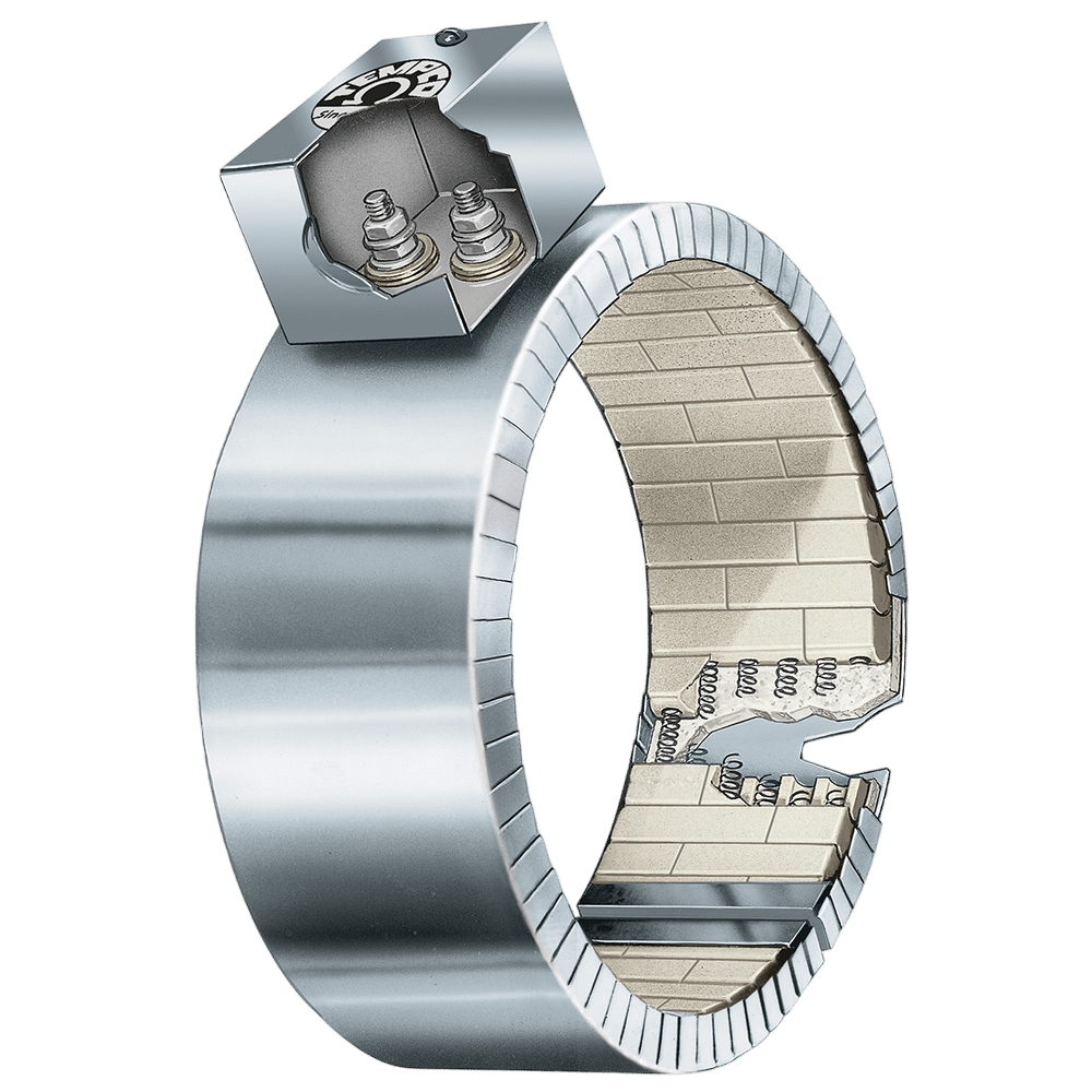
A helically wound resistance coil made from nickel-chrome wire is precisely strung through specially designed ceramic insulating bricks, forming a flexible heating mat. TEMPCO’s style of Ceramic Insulating Bricks offers several benefits including:
Excellent dielectric strength at high temperatures with high voltages
Ability to interlock and provide a more rigid structure
Allows for heater widths in smaller increments (1/8″)
Reduces the chances of damaging internal coils in transit and handling
Allows for easier installation of the heater onto the pipe
These heaters transmit heat through both conduction & radiation. The element winding is designed to heat the ceramic blocks to the point at which they radiate energy into the barrel as well as conduct energy by being in contact with the barrel – fit is not as critical as in other types of bands.
No options available for this section based on your selections
One-Piece Band
The One-Piece Ceramic Band Heater is the basic design most often specified by OEMs and processors. It is available with all types of insulation, construction styles, clamping or termination variations. Standard Insulation (S): 1/4″ Built-In ceramic fiber insulation ¼” thick standard on all Ceramic Bands will reduce power consumption by 25 to 30 percent, and lower external temperatures. See Additional Options > Construction Options for more insulation options
The One-Piece Ceramic Band Heater is the basic design most often specified by OEMs and processors. It is available with all types of insulation, construction styles, clamping or termination variations. Standard Insulation (S): 1/4″ Built-In ceramic fiber insulation ¼” thick standard on all Ceramic Bands will reduce power consumption by 25 to 30 percent, and lower external temperatures. See Additional Options > Construction Options for more insulation options
The Two-Piece Ceramic Band Heater is commonly used on sizes larger than 21″ diameter or when it would be inconvenient to use a one-piece heater. It is available with all types of insulation, construction styles, clamping or termination variations. Standard Insulation (S): 1/4″ Built-In ceramic fiber insulation ¼” thick standard on all Ceramic Bands will reduce power consumption by 25 to 30 percent, and lower external temperatures. See Additional Options > Construction Options for more insulation options
The Two-Piece Ceramic Band Heater is commonly used on sizes larger than 21″ diameter or when it would be inconvenient to use a one-piece heater. It is available with all types of insulation, construction styles, clamping or termination variations. Standard Insulation (S): 1/4″ Built-In ceramic fiber insulation ¼” thick standard on all Ceramic Bands will reduce power consumption by 25 to 30 percent, and lower external temperatures. See Additional Options > Construction Options for more insulation options
Limitations Minimum Inside Diameter: 4″ (101.6 mm) Minimum Width: 1″ (25.4 mm) Maximum Inside Diameter: 44″ (1118 mm)
Larger sizes are manufactured in multiple sections. Watts and volts are specified per each section when ordering.
Reverse Band
Reverse Ceramic Band Heaters are intended for the outer surface of the band to heat the inner surface of a cylinder. These heaters use the same built-in insulation as normal ceramic bands and therefor can either reduce the power needed to heat an application to the desired temperature or offer some thermal protection to anything else that might also be inside the cylinder. Standard Insulation (S): 1/4″ Built-In ceramic fiber insulation ¼” thick standard on all Ceramic Bands will reduce power consumption by 25 to 30 percent, and lower external temperatures.
Reverse Ceramic Band Heaters are intended for the outer surface of the band to heat the inner surface of a cylinder. These heaters use the same built-in insulation as normal ceramic bands and therefor can either reduce the power needed to heat an application to the desired temperature or offer some thermal protection to anything else that might also be inside the cylinder. Standard Insulation (S): 1/4″ Built-In ceramic fiber insulation ¼” thick standard on all Ceramic Bands will reduce power consumption by 25 to 30 percent, and lower external temperatures.
The specially designed internal brackets exert outward pressure to ensure good contact with the application surface. To aid in holding the internal components together during installation, reverse ceramic bands are supplied with a perforated stainless steel outer liner.
The outer diameter is the distinguishing characteristic and should match the inner diameter of the cylinder to be heated.
If airflow is needed for cooling, Tempco’s Type R Uninsulated Ceramic Band with a perforated sheath is also available. This is also the same robust construction that can reach higher temperatures than other heater bands.
No options available for this section based on your selections
Type B – Built-In Bracket (Standard), One-Piece Band
The Built-In Bracket is the basic design most often specified by OEMs and processors. The standard screw used is 1/4-20. It is available with all types of insulation, construction styles, and termination variations.
Type B – Built-In Bracket (Standard), One-Piece Band
The Built-In Bracket is the basic design most often specified by OEMs and processors. The standard screw used is 1/4-20. It is available with all types of insulation, construction styles, and termination variations.
Type B – Built-In Bracket (Standard), Two-Piece Band
The Built-In Bracket is the basic design most often specified by OEMs and processors. The standard screw used is 1/4-20. It is available with all types of insulation, construction styles, and termination variations.
Type B – Built-In Bracket (Standard), Two-Piece Band
The Built-In Bracket is the basic design most often specified by OEMs and processors. The standard screw used is 1/4-20. It is available with all types of insulation, construction styles, and termination variations.
Limitations
Minimum Inside Diameter: 4″ (101.6 mm)
Minimum Width: 1″ (25.4 mm
📦
Type S – Built-In Bracket with Spring-Loaded Screw, One-Piece Band
The Built-In Bracket can also be supplied with a spring- loaded screw. The spring-loaded clamp aids in absorbing thermal expansion.
Type S – Built-In Bracket with Spring-Loaded Screw, Two-Piece Band
The Built-In Bracket can also be supplied with a spring- loaded screw. The spring-loaded clamp aids in absorbing thermal expansion.
Limitations
Minimum Inside Diameter: 4″ (101.6 mm)
Minimum Width: 1″ (25.4 mm
Type L – Latch and Trunnion, One-Piece Band
The spring-loaded Latch and Trunnion clamping system is ideal for bands over 12″ in diameter to absorb thermal expansion and facilitate installation on large bands. The Latch and Trunnion clamping system is available with all types of insulation, construction styles, and termination variations.
The spring-loaded Latch and Trunnion clamping system is ideal for bands over 12″ in diameter to absorb thermal expansion and facilitate installation on large bands. The Latch and Trunnion clamping system is available with all types of insulation, construction styles, and termination variations.
Limitations
Minimum Inside Diameter: 4″ (101.6 mm)
Minimum Width: 1″ (25.4 mm)
📦
Type L – Latch and Trunnion, Two-Piece Band
The spring-loaded Latch and Trunnion clamping system is ideal for bands over 12″ in diameter to absorb thermal expansion and facilitate installation on large bands. The Latch and Trunnion clamping system is available with all types of insulation, construction styles, and termination variations.
The spring-loaded Latch and Trunnion clamping system is ideal for bands over 12″ in diameter to absorb thermal expansion and facilitate installation on large bands. The Latch and Trunnion clamping system is available with all types of insulation, construction styles, and termination variations.
The Shell Overlap design is the preferred method of providing a thermocouple mounting hole in a ceramic band heater. It is available with all types of insulation, construction styles, clamping and termination variations.
The Shell Overlap design is the preferred method of providing a thermocouple mounting hole in a ceramic band heater. It is available with all types of insulation, construction styles, clamping and termination variations.
The Shell Overlap design is the preferred method of providing a thermocouple mounting hole in a ceramic band heater. It is available with all types of insulation, construction styles, clamping and termination variations.
The Shell Overlap design is the preferred method of providing a thermocouple mounting hole in a ceramic band heater. It is available with all types of insulation, construction styles, clamping and termination variations.
Standard Termination Location: opposite the gap; center of width
Minimum Inside Diameter: 2″ (50.8 mm)
Minimum Width: 1″ (25.4 mm)
Maximum Volts/Amps: 480VAC/25A
Type T2 Screw Terminals are available with all types of insulation, construction styles, and clamping variations. They are considered to be standard on most band heaters under 2″ in width unless otherwise specified. 10-32 post terminals are standard.
Not available for Reverse Construction.
Type T2: Screw Terminals, Two-Piece Band
Standard Termination Location: center of each half; center of width
Standard Termination Location: center of each half; center of width
Minimum Inside Diameter: 4″ (101.6 mm)
Minimum Width: 1″ (25.4 mm)
Maximum Volts/Amps: 480VAC/25A each half
Type T2 Screw Terminals are available with all types of insulation, construction styles, and clamping variations. They are considered to be standard on most band heaters under 2″ in width unless otherwise specified. 10-32 post terminals are standard.
Not available for Reverse Construction.
Type T3: Screw Terminals, One-Piece Band
Standard Termination Location: opposite the gap; across center of width
Type T3 Screw Terminals are available with all types of insulation, construction styles, and clamping variations. They are considered to be standard on most band heaters unless otherwise specified. For use with leads, crimp terminals, or bus bars.
Type T3: Screw Terminals, Two-Piece Band
Standard Termination Location: center of each half; across center of width
Type T3 Screw Terminals are available with all types of insulation, construction styles, and clamping variations. They are considered to be standard on most band heaters unless otherwise specified. For use with leads, crimp terminals, or bus bars.
Type L1: Straight Lead Wires, One-Piece Band
Standard Termination Location: opposite the gap; center of width
Type L1 Straight Lead Wires are available with all types of insulation, construction styles, and clamping variations. They are used primarily on small diameter bands where clearance is limited. If applicable, screw terminals should always be specified due to the high heat generated by ceramic bands. The standard flexible leads are 10″ long.
Type L1: Straight Lead Wires, Two-Piece Band
Standard Termination Location: center of each half; center of width
Type L1 Straight Lead Wires are available with all types of insulation, construction styles, and clamping variations. They are used primarily on small diameter bands where clearance is limited. If applicable, screw terminals should always be specified due to the high heat generated by ceramic bands. The standard flexible leads are 10″ long.
Type W1: Abrasion Resistant Straight Wire Braid Leads, One-Piece Band
Standard Termination Location: opposite the gap; center of width
Straight Wire Braid Leads are available with all types of insulation, construction styles, and clamping variations. Wire braid leads offer sharp bending not possible with armor cable. If applicable, screw terminals should always be specified due to the high heat generated by ceramic bands. The standard leads are 10″ of wire braid over 12″ of flexible leads.
Stainless steel construction may be required for widths of 7/8″ (22.2 mm) to 1-5/8″ (41.3 mm).
Type W1: Abrasion Resistant Straight Wire Braid Leads, Two-Piece Band
Standard Termination Location: center of each half; center of width
Straight Wire Braid Leads are available with all types of insulation, construction styles, and clamping variations. Wire braid leads offer sharp bending not possible with armor cable. If applicable, screw terminals should always be specified due to the high heat generated by ceramic bands. The standard leads are 10″ of wire braid over 12″ of flexible leads.
Type W2M: Right-Angle Wire Braid Leads, 90° to Heater, One-Piece Band
Standard Termination Location: opposite the gap; center of width
Stainless Steel Wire Braid exits perpendicular to the heater centerline through a low profile stainless steel cap. This cap acts as a strain relief which protects against excessive flexing or pulling of the lead wire. The standard leads are 10″ of wire braid over 12″ of flexible leads.
If longer leads are required, specify when ordering.
Type W2M: Right-Angle Wire Braid Leads, 90° to Heater, Two-Piece Band
Standard Termination Location: center of each half; center of width
Stainless Steel Wire Braid exits perpendicular to the heater centerline through a low profile stainless steel cap. This cap acts as a strain relief which protects against excessive flexing or pulling of the lead wire. The standard leads are 10″ of wire braid over 12″ of flexible leads.
If longer leads are required, specify when ordering.
Type W5M: Right-Angle Wire Braid Leads, Parallel to Heater, One-Piece Band
Standard Termination Location: opposite the gap; center of width
Stainless Steel Wire Braid exits parallel to the heater centerline through a low profile stainless steel cap. This cap acts as a strain relief which protects against excessive flexing or pulling of the lead wire. The standard leads are 10″ of wire braid over 12″ of flexible leads.
If longer leads are required, specify when ordering.
Type W5M: Right-Angle Wire Braid Leads, Parallel to Heater, Two-Piece Band
Standard Termination Location: opposite the gap; center of width
Stainless Steel Wire Braid exits parallel to the heater centerline through a low profile stainless steel cap. This cap acts as a strain relief which protects against excessive flexing or pulling of the lead wire. The standard leads are 10″ of wire braid over 12″ of flexible leads.
If longer leads are required, specify when ordering.
Type R1: Abrasion Resistant Straight Armor Cable, One-Piece Band
Standard Termination Location: opposite the gap; center of width
Straight Armor Cable is available with all types of insulation, construction styles, and clamping variations. Armor cable provides far superior protection to lead wires where abrasion is a constant problem. If applicable, screw terminals should always be specified due to the high heat generated by ceramic bands. The standard leads are 10″ of armor cable over 12″ of flexible leads.
R1A – Galvanized Steel Armor Cable
R1B – Stainless Steel Armor Cable
Stainless steel construction may be required for widths of 7/8″ (22.2 mm) to 1-5/8″ (41.3 mm).
Type R1: Abrasion Resistant Straight Armor Cable, Two-Piece Band
Standard Termination Location: center of each half; center of width
Straight Armor Cable is available with all types of insulation, construction styles, and clamping variations. Armor cable provides far superior protection to lead wires where abrasion is a constant problem. If applicable, screw terminals should always be specified due to the high heat generated by ceramic bands. The standard leads are 10″ of armor cable over 12″ of flexible leads.
R1A – Galvanized Steel Armor Cable
R1B – Stainless Steel Armor Cable
Stainless steel construction may be required for widths of 7/8″ (22.2 mm) to 1-5/8″ (41.3 mm).
Type R2: Abrasion Resistant Right-Angle Armor Cable, One-Piece Band
Standard Termination Location: opposite the gap; center of width
Right-Angle Armor Cable is available with all types of insulation, construction styles, and clamping variations. It is used where space is limited and abrasion is a constant problem. If applicable, screw terminals should always be specified due to the high heat generated by ceramic bands. The standard leads are 10″ of armor cable over 12″ of flexible leads.
R2A – Galvanized Steel Armor Cable
R2B – Stainless Steel Armor Cable
Stainless steel construction may be required for widths of 7/8″ (22.2 mm) to 1-5/8″ (41.3 mm).
Type R2: Abrasion Resistant Right-Angle Armor Cable, Two-Piece Band
Standard Termination Location: center of each half; center of width
Right-Angle Armor Cable is available with all types of insulation, construction styles, and clamping variations. It is used where space is limited and abrasion is a constant problem. If applicable, screw terminals should always be specified due to the high heat generated by ceramic bands. The standard leads are 10″ of armor cable over 12″ of flexible leads.
R2A – Galvanized Steel Armor Cable
R2B – Stainless Steel Armor Cable
Stainless steel construction may be required for widths of 7/8″ (22.2 mm) to 1-5/8″ (41.3 mm).
Type S1: Lead Wire Spring Strain Relief, One-Piece Band
Standard Termination Location: opposite the gap; center of width
A strain relief spring is attached to the heater at the termination exit to reduce strain on leads subjected to excessive flexing. The spring is 2-5/8″ long. The flexible standard leads are 10″ long with 2-1/2″ of fiberglass sleeving.
S1A – Plain Leads and Strain Relief Spring
S1B – Stainless Steel Wire Braided Leads and Strain Relief Spring
Type S1: Lead Wire Spring Strain Relief, Two-Piece Band
Standard Termination Location: center of each half; center of width
A strain relief spring is attached to the heater at the termination exit to reduce strain on leads subjected to excessive flexing. The spring is 2-5/8″ long. The flexible standard leads are 10″ long with 2-1/2″ of fiberglass sleeving.
S1A – Plain Leads and Strain Relief Spring
S1B – Stainless Steel Wire Braided Leads and Strain Relief Spring
Type C2: Standard Terminal Box, One-Piece Band
Standard Termination Location: opposite the gap; center of width
Terminal Boxes are available with all types of insulation, construction styles, or clamping variations. It is a simple and economical way to protect employees from electric shock or prevent electric shorts that can result from exposed wiring on band heater electrical installations.
The Heavy Duty Terminal Boxes have a 1/2″ trade size knockout (actual diameter 7/8″) that will accept standard armor cable connectors. The boxes can be field assembled on band heaters that have a center distance between screws of 7/8″. To simplify installation the boxes can be pre-wired with galvanized armor, stainless steel armor, or wire braid.
C2A – Box only C2B – with galvanized armor C2C – with stainless steel armor C2D – with wire braid
Box Size: 1-1/2″H × 1-1/2″W × 2-1/2″L for bands 1-1/2″ to 2″ wide Box Size: 1-1/2″H × 2-1/8″W × 2-1/8″L for bands greater than 2″ wide
Heater dimensions will determine terminal configuration.
Type C2: Standard Terminal Box, Two-Piece Band
Standard Termination Location: center of each half; center of width
Terminal Boxes are available with all types of insulation, construction styles, or clamping variations. It is a simple and economical way to protect employees from electric shock or prevent electric shorts that can result from exposed wiring on band heater electrical installations.
The Heavy Duty Terminal Boxes have a 1/2″ trade size knockout (actual diameter 7/8″) that will accept standard armor cable connectors. The boxes can be field assembled on band heaters that have a center distance between screws of 7/8″. To simplify installation the boxes can be pre-wired with galvanized armor, stainless steel armor, or wire braid.
C2A – Box only C2B – with galvanized armor C2C – with stainless steel armor C2D – with wire braid
Box Size: 1-1/2″H × 1-1/2″W × 2-1/2″L for bands 1-1/2″ to 2″ wide Box Size: 1-1/2″H × 2-1/8″W × 2-1/8″L for bands greater than 2″ wide
Heater dimensions will determine terminal configuration.
Type C5: Low-Profile Terminal Box, One-Piece Band
Standard Termination Location: opposite the gap; center of width
Terminal Boxes are available with all types of insulation, construction styles, or clamping variations. It is a simple and economical way to protect employees from electric shock or prevent electric shorts that can result from exposed wiring on band heater electrical installations.
The Heavy Duty Terminal Boxes have a 1/2″ trade size knockout (actual diameter 7/8″) that will accept standard armor cable connectors. The boxes can be field assembled on band heaters that have a center distance between screws of 7/8″. To simplify installation the boxes can be pre-wired with galvanized armor, stainless steel armor, or wire braid.
C5A – Box only C5B – with galvanized armor C5C – with stainless steel armor C5D – with wire braid C5J – box with lead wire
Box Size: 1″H × 1-1/4″W × 3″L for bands 1-1/2″ to 2″ wide Box Size: 1″H × 2-1/4″W × 2″L for bands greater than 2″ wide
1. Heater dimensions will determine terminal configuration.
2. If a Low Profile Box with cable or leads is required, it is strongly recommended to order it pre-wired by the factory.
Type C5: Low-Profile Terminal Box, Two-Piece Band
Standard Termination Location: center of each half; center of width
Terminal Boxes are available with all types of insulation, construction styles, or clamping variations. It is a simple and economical way to protect employees from electric shock or prevent electric shorts that can result from exposed wiring on band heater electrical installations.
The Heavy Duty Terminal Boxes have a 1/2″ trade size knockout (actual diameter 7/8″) that will accept standard armor cable connectors. The boxes can be field assembled on band heaters that have a center distance between screws of 7/8″. To simplify installation the boxes can be pre-wired with galvanized armor, stainless steel armor, or wire braid.
C5A – Box only C5B – with galvanized armor C5C – with stainless steel armor C5D – with wire braid C5J – box with lead wire
Box Size: 1″H × 1-1/4″W × 3″L for bands 1-1/2″ to 2″ wide Box Size: 1″H × 2-1/4″W × 2″L for bands greater than 2″ wide
1. Heater dimensions will determine terminal configuration.
2. If a Low Profile Box with cable or leads is required, it is strongly recommended to order it pre-wired by the factory.
Type P1: Quick Disconnect Plugs, One-Piece Band
Standard Termination Location: opposite the gap; center of width
Minimum Width: 2″ (50.8 mm) depending on termination orientation
Quick Disconnect Plugs are available on any construction or clamping variation. These quick disconnect plug assemblies are highly recommended and should be used whenever possible. The combination of plug and cup assembly along with armor cable covered leads eliminates all live exposed terminals or wiring that can be a potential hazard to employees or machinery.
Type P1 assemblies are available with a straight or right-angle plug. To simplify installation, band heaters with these assemblies can be supplied pre-wired using high temperature lead wire protected with armor cable.
Plug Electrical Ratings 2-Pole 3-Wire Grounding
Maximum Volts: 250 VAC Maximum Amps: 16A Maximum Temperature: 392°F (200°C)
Minimum Width: 2″ (50.8 mm) depending on termination orientation
Quick Disconnect Plugs are available on any construction or clamping variation. These quick disconnect plug assemblies are highly recommended and should be used whenever possible. The combination of plug and cup assembly along with armor cable covered leads eliminates all live exposed terminals or wiring that can be a potential hazard to employees or machinery.
Type P1 assemblies are available with a straight or right-angle plug. To simplify installation, band heaters with these assemblies can be supplied pre-wired using high temperature lead wire protected with armor cable.
Plug Electrical Ratings
2-Pole 3-Wire Grounding
Maximum Volts: 250 VAC Maximum Amps: 16A Maximum Temperature: 392°F (200°C)
Type P2: Quick Disconnect Plugs, Low-Profile, One-Piece Band
Standard Termination Location: opposite the gap; center of width
Minimum Inside Diameter: 2″ (50.8 mm) Reverse Band: Consult Tempco with your requirements.
Minimum Width: 2″ (50.8 mm)
Quick Disconnect Plugs are available on any construction or clamping variation. These quick disconnect plug assemblies are highly recommended and should be used whenever possible. The combination of plug and cup assembly along with armor cable covered leads eliminates all live exposed terminals or wiring that can be a potential hazard to employees or machinery.
Type P2 plug assemblies have a lower profile and are available with a straight plug only.
Plug Electrical Ratings 2-Pole 3-Wire Grounding
Maximum Volts: 250 VAC Maximum Amps: 16A Maximum Temperature: 392°F (200°C)
Type P2: Quick Disconnect Plugs, Low-Profile, Two-Piece Band
Standard Termination Location: center of each half; center of width
Minimum Inside Diameter: 4″ (101.6 mm) Reverse Band: Consult Tempco with your requirements.
Minimum Width: 2″ (50.8 mm)
Quick Disconnect Plugs are available on any construction or clamping variation. These quick disconnect plug assemblies are highly recommended and should be used whenever possible. The combination of plug and cup assembly along with armor cable covered leads eliminates all live exposed terminals or wiring that can be a potential hazard to employees or machinery.
Type P2 plug assemblies have a lower profile and are available with a straight plug only.
Plug Electrical Ratings 2-Pole 3-Wire Grounding
Maximum Volts: 250 VAC Maximum Amps: 16A Maximum Temperature: 392°F (200°C)
Type P3: DIN 49458 A/B Quick Disconnect Plugs, Vertical, One-Piece Band
Standard Termination Location: opposite the gap; center of width
Minimum Inside Diameter: 3″ (76.2 mm) Reverse Band: Consult Tempco with your requirements.
Minimum Width: 2″ (50.8 mm)
Quick Disconnect Plugs are available on any construction or clamping variation. These quick disconnect plug assemblies are highly recommended and should be used whenever possible. The combination of plug and cup assembly along with armor cable covered leads eliminates all live exposed terminals or wiring that can be a potential hazard to employees or machinery.
Type P3 assemblies are available with a straight or right-angle plug. To simplify installation, band heaters with these assemblies can be supplied pre-wired using high temperature lead wire protected with armor cable.
Plug Electrical Ratings
2-Pole 3-Wire Grounding
Maximum Volts: 250 VAC
Maximum Amps: 16A
Maximum Temperature: 392°F (200°C)
P3A – Box assembly only
P3B – Box assembly w/straight plug
P3C – Box assembly w/right-angle plug
Type P3: DIN 49458 A/B Quick Disconnect Plugs, Vertical, Two-Piece Band
Standard Termination Location: center of each half; center of width
Minimum Inside Diameter: 4″ (101.6 mm) Reverse Band: Consult Tempco with your requirements.
Type P3: DIN 49458 A/B Quick Disconnect Plugs, Vertical, Two-Piece Band
Standard Termination Location: center of each half; center of width
Minimum Inside Diameter: 4″ (101.6 mm) Reverse Band: Consult Tempco with your requirements.
Minimum Width: 2″ (50.8 mm)
Quick Disconnect Plugs are available on any construction or clamping variation. These quick disconnect plug assemblies are highly recommended and should be used whenever possible. The combination of plug and cup assembly along with armor cable covered leads eliminates all live exposed terminals or wiring that can be a potential hazard to employees or machinery.
Type P3 assemblies are available with a straight or right-angle plug. To simplify installation, band heaters with these assemblies can be supplied pre-wired using high temperature lead wire protected with armor cable.
Plug Electrical Ratings
2-Pole 3-Wire Grounding
Maximum Volts: 250 VAC Maximum Amps: 16A Maximum Temperature: 392°F (200°C)
Type P4: DIN 49458 A/B Quick Disconnect Plugs, Horizontal, One-Piece Band
Standard Termination Location:opposite the gap; center of width
Minimum Inside Diameter: 2-1/2″ (63.5 mm) Reverse Band: Consult Tempco with your requirements.
Minimum Width: 2-1/2″ (63.5 mm)
Quick Disconnect Plugs are available on any construction or clamping variation. These quick disconnect plug assemblies are highly recommended and should be used whenever possible. The combination of plug and cup assembly along with armor cable covered leads eliminates all live exposed terminals or wiring that can be a potential hazard to employees or machinery.
Type P4 plug assemblies have a lower profile and are available with a straight plug only. To simplify installation, band heaters with these assemblies can be supplied pre-wired using high temperature lead wire protected with armor cable.
Plug Electrical Ratings 2-Pole 3-Wire Grounding Maximum Volts: 250 VAC Maximum Amps: 16A Maximum Temperature: 392°F (200°C)
Type P4: DIN 49458 A/B Quick Disconnect Plugs, Horizontal, Two-Piece Band
Standard Termination Location:center of each half; center of width
Minimum Inside Diameter: 4″ (101.6 mm) Reverse Band: Consult Tempco with your requirements.
Minimum Width: 2-1/2″ (63.5 mm)
Quick Disconnect Plugs are available on any construction or clamping variation. These quick disconnect plug assemblies are highly recommended and should be used whenever possible. The combination of plug and cup assembly along with armor cable covered leads eliminates all live exposed terminals or wiring that can be a potential hazard to employees or machinery.
Type P4 plug assemblies have a lower profile and are available with a straight plug only. To simplify installation, band heaters with these assemblies can be supplied pre-wired using high temperature lead wire protected with armor cable.
Plug Electrical Ratings
2-Pole 3-Wire Grounding
Maximum Volts: 250 VAC
Maximum Amps: 16A
Maximum Temperature: 392°F (200°C)
P4A – Box assembly only
P4B – Box assembly w/straight plug
Additional Options
No options available for this section based on your selections
Optional Double Insulation (D): 1/2
Standard built-In ceramic fiber insulation 1/4″ thick on all Ceramic Bands; will reduce power consumption by 25 to 30 percent and lower external temperatures (when compared to uninsulated band heaters). Optional built-in ceramic fiber insulation 1/2″ thick is available; for situations requiring additional insulation for lower external temperatures and increased electrical energy savings. This will decrease power consumption by 35 to 37 percent (when compared to uninsulated band heaters).
Standard built-In ceramic fiber insulation 1/4″ thick on all Ceramic Bands; will reduce power consumption by 25 to 30 percent and lower external temperatures (when compared to uninsulated band heaters). Optional built-in ceramic fiber insulation 1/2″ thick is available; for situations requiring additional insulation for lower external temperatures and increased electrical energy savings. This will decrease power consumption by 35 to 37 percent (when compared to uninsulated band heaters).
Not available for Reverse Construction.
📦
Type R: Uninsulated Ceramic Band Heaters
Type R Construction is an uninsulated ceramic band heater with a perforated Stainless Steel outer shell for more efficient cooling. It is typically used in multiple quantities with forced air cooling systems such as Tempco’s Cool TO-THE Touch Shroud Systems (see Type RCC below).
Type R Construction is an uninsulated ceramic band heater with a perforated Stainless Steel outer shell for more efficient cooling. It is typically used in multiple quantities with forced air cooling systems such as Tempco’s Cool TO-THE Touch Shroud Systems (see Type RCC below).
Performance Ratings Maximum Watt Density: 50 W/in2 (8 W/cm2) Maximum Temperature: 900°F (482°C)
Mechanical Ratings Standard Width Increments: 1/8″ 3.2 cm Maximum Width: depends on ratio of diameter to width Minimum Width: 1″ (25.4 mm) Standard Gap: 3/8″ ±1/8″ (9.5 ±3.2 mm)
Electrical Ratings
Resistance tolerance: +10%, –5% Wattage tolerance: +5%, –10% Maximum Voltage: 480 single or 3-phase (when applicable) Maximum Amperage: Screw Terminals: 25 Amps per circuit Lead Wire: 10 Amps per circuit
📦
Type RCC: (Ribcage) Heating Mounting Configuration
This system was developed to reduce the cost and weight of typical shroud systems for the heating and cooling of high temperature extrusion processes.Type RCC (Rib Cage) Air Cooled Systems use multiple Type R Ceramic Band Heaters under one shroud. See also Shroud Systems.
These low mass, non-thermally insulated ceramic band heaters work in tandem with a highly efficient stainless steel sheet metal shroud and are typically arranged with spaces between the heaters to enhance the cooling of the barrel when external heat is no longer required.
Forced air blowers are used for cooling. The ambient airflow enters the shroud, circulates around the ceramic heater and barrel, removes the heat from the heater and the process and exits the shroud opposite the entrance port.
The Cool TO-THE Touch dual layer shroud uses an inner stainless steel solid layer thermally isolated from the heater, providing a path for the forced cooling air. An outer Stainless Steel perforated layer provides optimal venting and heat dissipation while providing personnel safety.
Igloo® Ceramic Terminal Covers
Igloo™ Ceramic Terminal Covers consist of two individual ceramic parts. They are available with all types of insulation, construction styles, and clamping variations. Unlike conventional ceramic caps, Igloo fully insulates any standard #10 terminal lugs used for electrical hook-ups.
Igloo™ Ceramic Terminal Covers consist of two individual ceramic parts. They are available with all types of insulation, construction styles, and clamping variations. Unlike conventional ceramic caps, Igloo fully insulates any standard #10 terminal lugs used for electrical hook-ups.
Limitations
One-Piece Band with Type T2 or Type T3 Screw Terminals Minimum Inner Diamter: 2″ (50.8 mm) Minimum Width: 1″ (25.4 mm) Two-Piece Band with Type T2 or Type T3 Screw Terminals Minimum Inner Diamter: 4″ (101.6 mm) Min. Width: 1″ (25.4 mm) Reverse Band with Type T3 Screw Terminals Minimum Inner Diamter: 5-1/2″ (139.7 mm)
Three types of Igloo™ bases are available: Type C6— Double Port In-Line P/N CER-101-104 Type C7 — Double Port 90° P/N CER-101-106 Type C8 — Single Port P/N CER-101-107
Igloo™ caps are available in the following screw terminal size: 10-32 — P/N CER-102-101
📦
Three-Phase
On very high wattage band heaters it would be advantageous to set up the wiring three-phase to reduce the current load across a single conductor. Three-phase wiring is available with all types of insulation, construction styles, and clamping variations. Minimum width: 3″ (76.2 mm)
On very high wattage band heaters it would be advantageous to set up the wiring three-phase to reduce the current load across a single conductor. Three-phase wiring is available with all types of insulation, construction styles, and clamping variations. Minimum width: 3″ (76.2 mm)
📦
Dual Voltage
Band heaters can be designed using 3-wire series/parallel circuits for dual voltage applications. Whether the heater is run on the high or low voltage, the wattage will be the same. Dual Voltage wiring is available with all types of insulation, construction styles, or clamping variations. Minimum width: 2″ (50.8 mm)
Band heaters can be designed using 3-wire series/parallel circuits for dual voltage applications. Whether the heater is run on the high or low voltage, the wattage will be the same. Dual Voltage wiring is available with all types of insulation, construction styles, or clamping variations. Minimum width: 2″ (50.8 mm)
📦
Single-Phase/Three-Phase
Ceramic Band Heaters can be designed with multiple circuits to operate single or three-phase.
Ceramic Band Heaters can be designed with multiple circuits to operate single or three-phase.
📦
Electrical Plugs
Industry standard NEMA twist lock electrical connectors are available. The plugs can be attached to fiberglass leads, armor cable or wire braid. Electrical Plugs can be added to any termination variation.
Industry standard NEMA twist lock electrical connectors are available. The plugs can be attached to fiberglass leads, armor cable or wire braid. Electrical Plugs can be added to any termination variation.
📦
Terminal Lugs
Various types of crimp terminals can be attached to the heater leads to make wiring into applications quick and easy. High temperature [1200°F (649°C)] ring terminals and nylon or PVC insulated terminals are available. Spade, ring, and right-angle or straight quick disconnect type terminals can be attached to the leads.
Various types of crimp terminals can be attached to the heater leads to make wiring into applications quick and easy. High temperature [1200°F (649°C)] ring terminals and nylon or PVC insulated terminals are available. Spade, ring, and right-angle or straight quick disconnect type terminals can be attached to the leads.
📦
High Temperature Lead Wire
When required, high temperature lead wire can be used. The wire is insulated with mica tapes over the stranded nickel conductors and then treated fiberglass overbraid. Maximum temperature: 450°C (842°F)
When required, high temperature lead wire can be used. The wire is insulated with mica tapes over the stranded nickel conductors and then treated fiberglass overbraid. Maximum temperature: 450°C (842°F)
📦
Ground Terminal or Lead
For those applications requiring a separate ground terminal or lead attached to the heater sheath. A Ground Terminal or Lead is available on any construction or termination variation.
For those applications requiring a separate ground terminal or lead attached to the heater sheath. A Ground Terminal or Lead is available on any construction or termination variation.
📦
Oversize Gap
The nominal gap is 3/8″. If a larger gap is required for probes or thermocouples, specify when ordering.
Type W5M: Right-Angle Wire Braid Leads, Parallel to Heater, Two-Piece Band Standard Termination Location: opposite the gap; center of width Minimum Inside Diameter: 2″ (50.8 mm) Reverse Band: 5-1/2″ (139.7 mm) Minimum Width: 1″ (25.4 mm) Maximum Volts/Amps: 480VAC/12.5A Stainless Steel Wire Braid exits parallel to the heater centerline through a low profile stainless steel cap. This cap acts as a strain relief which protects against excessive flexing or pulling of the lead wire. The standard leads are 10″ of wire braid over 12″ of flexible leads. If longer leads are required, specify when ordering. Electrical Terminations 1 Piece Additional Options Brackets Clamping Options Construction Options Construction Styles Electrical Variations Flange Latch and Trunnion Lead Variations Reverse Band Shell Overlap Terminal Covers Wire Braids Type W5M: Right-Angle Wire Braid Leads, Parallel to Heater, One-Piece Band Type W2M: Right-Angle Wire Braid Leads, 90° to Heater, Two-Piece Band Standard Termination Location: center of each half; center of width Minimum Inside Diameter: 4″ (101.6 mm) Reverse Band: 5-1/2″ (139.7 mm) Minimum Width: 1″ (25.4 mm) Maximum Volts/Amps: 480VAC/12.5A each half Stainless Steel Wire Braid exits perpendicular to the heater centerline through a low profile stainless steel cap. This cap acts as a strain relief which protects against excessive flexing or pulling of the lead wire. The standard leads are 10″ of wire braid over 12″ of flexible leads. 2 Piece Type W2M: Right-Angle Wire Braid Leads, 90° to Heater, One-Piece Band Type W1: Abrasion Resistant Straight Wire Braid Leads, Two-Piece Band Straight Wire Braid Leads are available with all types of insulation, construction styles, and clamping variations. Wire braid leads offer sharp bending not possible with armor cable. If applicable, screw terminals should always be specified due to the high heat generated by ceramic bands. The standard leads are 10″ of wire braid over 12″ of flexible leads. Type W1: Abrasion Resistant Straight Wire Braid Leads, One-Piece Band Stainless steel construction may be required for widths of 7/8" (22.2 mm) to 1-5/8" (41.3 mm). Type T3: Screw Terminals, Two-Piece Band Standard Termination Location: center of each half; across center of width Minimum Inside Diameter: 4″ (101.6 mm) Reverse Band: 5-1/2″ (139.7 mm) Minimum Width: 2″ (50.8 mm) Maximum Volts/Amps: 480VAC/25A each half Type T3 Screw Terminals are available with all types of insulation, construction styles, and clamping variations. They are considered to be standard on most band heaters unless otherwise specified. For use with leads, crimp terminals, or bus bars. Screw Terminals Type T3: Screw Terminals, One-Piece Band Standard Termination Location: opposite the gap; across center of width Minimum Inside Diameter: 2″ (50.8 mm) Reverse Band: 5-1/2″ (139.7 mm) Minimum Width: 2″ (50.8 mm) Maximum Volts/Amps: 480VAC/25A Type T2: Screw Terminals, Two-Piece Band Standard Termination Location: center of each half; center of width Minimum Inside Diameter: 4″ (101.6 mm) Minimum Width: 1″ (25.4 mm) Maximum Volts/Amps: 480VAC/25A each half Type T2 Screw Terminals are available with all types of insulation, construction styles, and clamping variations. They are considered to be standard on most band heaters under 2″ in width unless otherwise specified. 10-32 post terminals are standard. Not available for Reverse Construction. Type T2: Screw Terminals, One-Piece Band Standard Termination Location: opposite the gap; center of width Minimum Inside Diameter: 2″ (50.8 mm) Minimum Width: 1″ (25.4 mm) Maximum Volts/Amps: 480VAC/25A Type S1: Lead Wire Spring Strain Relief, Two-Piece Band A strain relief spring is attached to the heater at the termination exit to reduce strain on leads subjected to excessive flexing. The spring is 2-5/8″ long. The flexible standard leads are 10″ long with 2-1/2″ of fiberglass sleeving. S1A – Plain Leads and Strain Relief Spring S1B – Stainless Steel Wire Braided Leads and Strain Relief Spring Lead Wire Type S1: Lead Wire Spring Strain Relief, One-Piece Band A strain relief spring is attached to the heater at the termination exit to reduce strain on leads subjected to excessive flexing. The spring is 2-5/8″ long. The flexible standard leads are 10″ long with 2-1/2″ of fiberglass sleeving. S1A – Plain Leads and Strain Relief Spring S1B – Stainless Steel Wire Braided Leads and Strain Relief Spring Type S – Built-In Bracket with Spring-Loaded Screw, One-Piece Band The Built-In Bracket can also be supplied with a spring- loaded screw. The spring-loaded clamp aids in absorbing thermal expansion. Limitations Minimum Inside Diameter: 2″ (50.8 mm) Minimum Width: 1″ (25.4 mm) Armor Cable Quick Disconnect Plugs Terminal Housings Type S – Built-In Bracket with Spring-Loaded Screw, Two-Piece Band Limitations Minimum Inside Diameter: 4″ (101.6 mm) Minimum Width: 1″ (25.4 mm Type RCC: (Ribcage) Heating Mounting Configuration This system was developed to reduce the cost and weight of typical shroud systems for the heating and cooling of high temperature extrusion processes.Type RCC (Rib Cage) Air Cooled Systems use multiple Type R Ceramic Band Heaters under one shroud. See also Shroud Systems. These low mass, non-thermally insulated ceramic band heaters work in tandem with a highly efficient stainless steel sheet metal shroud and are typically arranged with spaces between the heaters to enhance the cooling of the barrel when external heat is no longer required. Forced air blowers are used for cooling. The ambient airflow enters the shroud, circulates around the ceramic heater and barrel, removes the heat from the heater and the process and exits the shroud opposite the entrance port. The Cool TO-THE Touch dual layer shroud uses an inner stainless steel solid layer thermally isolated from the heater, providing a path for the forced cooling air. An outer Stainless Steel perforated layer provides optimal venting and heat dissipation while providing personnel safety. Type R2: Abrasion Resistant Right-Angle Armor Cable, Two-Piece Band Right-Angle Armor Cable is available with all types of insulation, construction styles, and clamping variations. It is used where space is limited and abrasion is a constant problem. If applicable, screw terminals should always be specified due to the high heat generated by ceramic bands. The standard leads are 10″ of armor cable over 12″ of flexible leads. R2A – Galvanized Steel Armor Cable R2B – Stainless Steel Armor Cable Type R2: Abrasion Resistant Right-Angle Armor Cable, One-Piece Band Standard Termination Location: opposite the gap; center of width Minimum Inside Diameter: 2″ (50.8 mm) Reverse Band: 5-1/2″ (139.7 mm) Minimum Width: 1″ (25.4 mm) Maximum Volts/Amps: 480VAC/12A Type R1: Abrasion Resistant Straight Armor Cable, Two-Piece Band Straight Armor Cable is available with all types of insulation, construction styles, and clamping variations. Armor cable provides far superior protection to lead wires where abrasion is a constant problem. If applicable, screw terminals should always be specified due to the high heat generated by ceramic bands. The standard leads are 10″ of armor cable over 12″ of flexible leads. R1A – Galvanized Steel Armor Cable R1B – Stainless Steel Armor Cable Type R1: Abrasion Resistant Straight Armor Cable, One-Piece Band Type R: Uninsulated Ceramic Band Heaters Type R Construction is an uninsulated ceramic band heater with a perforated Stainless Steel outer shell for more efficient cooling. It is typically used in multiple quantities with forced air cooling systems such as Tempco’s Cool TO-THE Touch Shroud Systems (see Type RCC below). Performance Ratings Maximum Watt Density: 50 W/in2 (8 W/cm2) Maximum Temperature: 900°F (482°C) Mechanical Ratings Standard Width Increments: 1/8″ 3.2 cm Maximum Width: depends on ratio of diameter to width Minimum Width: 1″ (25.4 mm) Standard Gap: 3/8″ ±1/8″ (9.5 ±3.2 mm) Electrical Ratings Resistance tolerance: +10%, –5% Wattage tolerance: +5%, –10% Maximum Voltage: 480 single or 3-phase (when applicable) Maximum Amperage: Screw Terminals: 25 Amps per circuit Lead Wire: 10 Amps per circuit Type P4: DIN 49458 A/B Quick Disconnect Plugs, Horizontal, Two-Piece Band Standard Termination Location:center of each half; center of width Minimum Inside Diameter: 4″ (101.6 mm) Reverse Band: Consult Tempco with your requirements. Minimum Width: 2-1/2″ (63.5 mm) Quick Disconnect Plugs are available on any construction or clamping variation. These quick disconnect plug assemblies are highly recommended and should be used whenever possible. The combination of plug and cup assembly along with armor cable covered leads eliminates all live exposed terminals or wiring that can be a potential hazard to employees or machinery. Type P4 plug assemblies have a lower profile and are available with a straight plug only. To simplify installation, band heaters with these assemblies can be supplied pre-wired using high temperature lead wire protected with armor cable. Plug Electrical Ratings 2-Pole 3-Wire Grounding Maximum Volts: 250 VAC Maximum Amps: 16A Maximum Temperature: 392°F (200°C) P4A – Box assembly only P4B – Box assembly w/straight plug Type P4: DIN 49458 A/B Quick Disconnect Plugs, Horizontal, One-Piece Band Standard Termination Location:opposite the gap; center of width Minimum Inside Diameter: 2-1/2″ (63.5 mm) Reverse Band: Consult Tempco with your requirements. Minimum Width: 2-1/2″ (63.5 mm) Quick Disconnect Plugs are available on any construction or clamping variation. These quick disconnect plug assemblies are highly recommended and should be used whenever possible. The combination of plug and cup assembly along with armor cable covered leads eliminates all live exposed terminals or wiring that can be a potential hazard to employees or machinery. Type P4 plug assemblies have a lower profile and are available with a straight plug only. To simplify installation, band heaters with these assemblies can be supplied pre-wired using high temperature lead wire protected with armor cable. Plug Electrical Ratings 2-Pole 3-Wire Grounding Maximum Volts: 250 VAC Maximum Amps: 16A Maximum Temperature: 392°F (200°C) P4A – Box assembly only P4B – Box assembly w/straight plug Type P3: DIN 49458 A/B Quick Disconnect Plugs, Vertical, Two-Piece Band Standard Termination Location: center of each half; center of width Minimum Inside Diameter: 4″ (101.6 mm) Reverse Band: Consult Tempco with your requirements. Minimum Width: 2″ (50.8 mm) Quick Disconnect Plugs are available on any construction or clamping variation. These quick disconnect plug assemblies are highly recommended and should be used whenever possible. The combination of plug and cup assembly along with armor cable covered leads eliminates all live exposed terminals or wiring that can be a potential hazard to employees or machinery. Type P3 assemblies are available with a straight or right-angle plug. To simplify installation, band heaters with these assemblies can be supplied pre-wired using high temperature lead wire protected with armor cable. Plug Electrical Ratings 2-Pole 3-Wire Grounding Maximum Volts: 250 VAC Maximum Amps: 16A Maximum Temperature: 392°F (200°C) P3A – Box assembly only P3B – Box assembly w/straight plug P3C – Box assembly w/right-angle plug Type P3: DIN 49458 A/B Quick Disconnect Plugs, Vertical, One-Piece Band Standard Termination Location: opposite the gap; center of width Minimum Inside Diameter: 3″ (76.2 mm) Reverse Band: Consult Tempco with your requirements. Minimum Width: 2″ (50.8 mm) Quick Disconnect Plugs are available on any construction or clamping variation. These quick disconnect plug assemblies are highly recommended and should be used whenever possible. The combination of plug and cup assembly along with armor cable covered leads eliminates all live exposed terminals or wiring that can be a potential hazard to employees or machinery. Type P3 assemblies are available with a straight or right-angle plug. To simplify installation, band heaters with these assemblies can be supplied pre-wired using high temperature lead wire protected with armor cable. Plug Electrical Ratings 2-Pole 3-Wire Grounding Maximum Volts: 250 VAC Maximum Amps: 16A Maximum Temperature: 392°F (200°C) P3A – Box assembly only P3B – Box assembly w/straight plug P3C – Box assembly w/right-angle plug Type P2: Quick Disconnect Plugs, Low-Profile, Two-Piece Band Quick Disconnect Plugs are available on any construction or clamping variation. These quick disconnect plug assemblies are highly recommended and should be used whenever possible. The combination of plug and cup assembly along with armor cable covered leads eliminates all live exposed terminals or wiring that can be a potential hazard to employees or machinery. Type P2 plug assemblies have a lower profile and are available with a straight plug only. Plug Electrical Ratings 2-Pole 3-Wire Grounding Maximum Volts: 250 VAC Maximum Amps: 16A Maximum Temperature: 392°F (200°C) P1K – Cup Assembly only P1L – w/straight plug only P1M – w/90° plug only P1N – w/straight plug & galvanized armor cable P1O – w/straight plug & stainless steel armor cable P1P – w/straight plug & wire braid P1Q – w/90° plug & galvanized armor cable P1R – w/90° plug & stainless steel armor cable P1S – w/90° plug & wire braid Type P2: Quick Disconnect Plugs, Low-Profile, One-Piece Band Standard Termination Location: opposite the gap; center of width Minimum Inside Diameter: 2″ (50.8 mm) Reverse Band: Consult Tempco with your requirements. Minimum Width: 2″ (50.8 mm) Quick Disconnect Plugs are available on any construction or clamping variation. These quick disconnect plug assemblies are highly recommended and should be used whenever possible. The combination of plug and cup assembly along with armor cable covered leads eliminates all live exposed terminals or wiring that can be a potential hazard to employees or machinery. Type P2 plug assemblies have a lower profile and are available with a straight plug only. Plug Electrical Ratings 2-Pole 3-Wire Grounding Maximum Volts: 250 VAC Maximum Amps: 16A Maximum Temperature: 392°F (200°C) P1K – Cup Assembly only P1L – w/straight plug only P1M – w/90° plug only P1N – w/straight plug & galvanized armor cable P1O – w/straight plug & stainless steel armor cable P1P – w/straight plug & wire braid P1Q – w/90° plug & galvanized armor cable/ P1R – w/90° plug & stainless steel armor cable P1S – w/90° plug & wire braid Type P1: Quick Disconnect Plugs, One-Piece Band Standard Termination Location: opposite the gap; center of width Minimum Inside Diameter: 2″ (50.8 mm) Reverse Band: 5-1/2″ (139.7 mm) Minimum Width: 2″ (50.8 mm) depending on termination orientation Quick Disconnect Plugs are available on any construction or clamping variation. These quick disconnect plug assemblies are highly recommended and should be used whenever possible. The combination of plug and cup assembly along with armor cable covered leads eliminates all live exposed terminals or wiring that can be a potential hazard to employees or machinery. Type P1 assemblies are available with a straight or right-angle plug. To simplify installation, band heaters with these assemblies can be supplied pre-wired using high temperature lead wire protected with armor cable. Plug Electrical Ratings 2-Pole 3-Wire Grounding Maximum Volts: 250 VAC Maximum Amps: 16A Maximum Temperature: 392°F (200°C) P1K – Cup Assembly only P1L – w/straight plug only P1M – w/90° plug only P1N – w/straight plug & galvanized armor cable P1O – w/straight plug & stainless steel armor cable P1P – w/straight plug & wire braid P1Q – w/90° plug & galvanized armor cable P1R – w/90° plug & stainless steel armor cable P1S – w/90° plug & wire braid Type P1: Quick Disconnect Plugs, Two-Piece Band Standard Termination Location: center of each half; center of width Minimum Inside Diameter: 4″ (101.6 mm) Reverse Band: 5-1/2″ (139.7 mm) Minimum Width: 2″ (50.8 mm) depending on termination orientation Quick Disconnect Plugs are available on any construction or clamping variation. These quick disconnect plug assemblies are highly recommended and should be used whenever possible. The combination of plug and cup assembly along with armor cable covered leads eliminates all live exposed terminals or wiring that can be a potential hazard to employees or machinery. Type P1 assemblies are available with a straight or right-angle plug. To simplify installation, band heaters with these assemblies can be supplied pre-wired using high temperature lead wire protected with armor cable. Plug Electrical Ratings 2-Pole 3-Wire Grounding Maximum Volts: 250 VAC Maximum Amps: 16A Maximum Temperature: 392°F (200°C) P1K – Cup Assembly only P1L – w/straight plug only P1M – w/90° plug only P1N – w/straight plug & galvanized armor cable P1O – w/straight plug & stainless steel armor cable P1P – w/straight plug & wire braid P1Q – w/90° plug & galvanized armor cable P1R – w/90° plug & stainless steel armor cable P1S – w/90° plug & wire braid Type L1: Straight Lead Wires, Two-Piece Band Type L1 Straight Lead Wires are available with all types of insulation, construction styles, and clamping variations. They are used primarily on small diameter bands where clearance is limited. If applicable, screw terminals should always be specified due to the high heat generated by ceramic bands. The standard flexible leads are 10″ long. Type L1: Straight Lead Wires, One-Piece Band Type L – Latch and Trunnion, Two-Piece Band The spring-loaded Latch and Trunnion clamping system is ideal for bands over 12″ in diameter to absorb thermal expansion and facilitate installation on large bands. The Latch and Trunnion clamping system is available with all types of insulation, construction styles, and termination variations. Limitations Minimum Inside Diameter: 4″ (101.6 mm) Minimum Width: 2″ (50.8 mm) Type L – Latch and Trunnion, One-Piece Band Limitations Minimum Inside Diameter: 4″ (101.6 mm) Minimum Width: 1″ (25.4 mm) Type F – Bent-Up Flange (Ears), Two-Piece Band The Bent-Up Flange (Ears) design is available with all types of insulation, construction styles, and termination variations. Limitations Minimum Inside Diameter: 4″ (101.6 mm) Minimum Width: 2.5″ (63.5 mm) Type F – Bent-Up Flange (Ears), One-Piece Band Limitations Minimum Inside Diameter: 2″ (50.8 mm) Minimum Width: 1″ (25.4 mm) Type C5: Low-Profile Terminal Box, Two-Piece Band Standard Termination Location: center of each half; center of width Minimum Inside Diameter: 4″ (101.6 mm) Reverse Band: 15″ (381 mm) Minimum Width: 1-1/2″ (38.1 mm) Maximum Volts/Amps: 480VAC/25A each half Terminal Boxes are available with all types of insulation, construction styles, or clamping variations. It is a simple and economical way to protect employees from electric shock or prevent electric shorts that can result from exposed wiring on band heater electrical installations. The Heavy Duty Terminal Boxes have a 1/2″ trade size knockout (actual diameter 7/8″) that will accept standard armor cable connectors. The boxes can be field assembled on band heaters that have a center distance between screws of 7/8″. To simplify installation the boxes can be pre-wired with galvanized armor, stainless steel armor, or wire braid. C5A – Box only C5B – with galvanized armor C5C – with stainless steel armor C5D – with wire braid C5J – box with lead wire Box Size: 1″H × 1-1/4″W × 3″L for bands 1-1/2″ to 2″ wide Box Size: 1″H × 2-1/4″W × 2″L for bands greater than 2″ wide 1. Heater dimensions will determine terminal configuration. 2. If a Low Profile Box with cable or leads is required, it is strongly recommended to order it pre-wired by the factory. Type C5: Low-Profile Terminal Box, One-Piece Band Standard Termination Location: opposite the gap; center of width Minimum Inside Diameter: 2″ (50.8 mm) Reverse Band: 15″ (381 mm) Minimum Width: 1-1/2″ (38.1 mm) Maximum Volts/Amps: 480VAC/25A Terminal Boxes are available with all types of insulation, construction styles, or clamping variations. It is a simple and economical way to protect employees from electric shock or prevent electric shorts that can result from exposed wiring on band heater electrical installations. The Heavy Duty Terminal Boxes have a 1/2″ trade size knockout (actual diameter 7/8″) that will accept standard armor cable connectors. The boxes can be field assembled on band heaters that have a center distance between screws of 7/8″. To simplify installation the boxes can be pre-wired with galvanized armor, stainless steel armor, or wire braid. C5A – Box only C5B – with galvanized armor C5C – with stainless steel armor C5D – with wire braid C5J – box with lead wire Box Size: 1″H × 1-1/4″W × 3″L for bands 1-1/2″ to 2″ wide Box Size: 1″H × 2-1/4″W × 2″L for bands greater than 2″ wide Type C2: Standard Terminal Box, Two-Piece Band Terminal Boxes are available with all types of insulation, construction styles, or clamping variations. It is a simple and economical way to protect employees from electric shock or prevent electric shorts that can result from exposed wiring on band heater electrical installations. The Heavy Duty Terminal Boxes have a 1/2″ trade size knockout (actual diameter 7/8″) that will accept standard armor cable connectors. The boxes can be field assembled on band heaters that have a center distance between screws of 7/8″. To simplify installation the boxes can be pre-wired with galvanized armor, stainless steel armor, or wire braid. C2A – Box only C2B – with galvanized armor C2C – with stainless steel armor C2D – with wire braid Box Size: 1-1/2″H × 1-1/2″W × 2-1/2″L for bands 1-1/2″ to 2″ wide Box Size: 1-1/2″H × 2-1/8″W × 2-1/8″L for bands greater than 2″ wide Heater dimensions will determine terminal configuration. Type C2: Standard Terminal Box, One-Piece Band Standard Termination Location: opposite the gap; center of width Minimum Inside Diameter: 2″ (50.8 mm) Reverse Band: 15″ (381 mm) Minimum Width: 1-1/2″ (38.1 mm) Maximum Volts/Amps: 480VAC/25A Terminal Boxes are available with all types of insulation, construction styles, or clamping variations. It is a simple and economical way to protect employees from electric shock or prevent electric shorts that can result from exposed wiring on band heater electrical installations. The Heavy Duty Terminal Boxes have a 1/2″ trade size knockout (actual diameter 7/8″) that will accept standard armor cable connectors. The boxes can be field assembled on band heaters that have a center distance between screws of 7/8″. To simplify installation the boxes can be pre-wired with galvanized armor, stainless steel armor, or wire braid. C2A – Box only C2B – with galvanized armor C2C – with stainless steel armor C2D – with wire braid Box Size: 1-1/2″H × 1-1/2″W × 2-1/2″L for bands 1-1/2″ to 2″ wide Box Size: 1-1/2″H × 2-1/8″W × 2-1/8″L for bands greater than 2″ wide Type B – Built-In Bracket (Standard), One-Piece Band The Built-In Bracket is the basic design most often specified by OEMs and processors. The standard screw used is 1/4-20. It is available with all types of insulation, construction styles, and termination variations. Type B – Built-In Bracket (Standard), Two-Piece Band Two-Piece Band The Two-Piece Ceramic Band Heater is commonly used on sizes larger than 21″ diameter or when it would be inconvenient to use a one-piece heater. It is available with all types of insulation, construction styles, clamping or termination variations. Standard Insulation (S): 1/4″ Built-In ceramic fiber insulation ¼” thick standard on all Ceramic Bands will reduce power consumption by 25 to 30 percent, and lower external temperatures. See Additional Options > Construction Options for more insulation options Limitations Minimum Inside Diameter: 4″ (101.6 mm) Minimum Width: 1″ (25.4 mm) Maximum Inside Diameter: 44″ (1118 mm) Larger sizes are manufactured in multiple sections. Watts and volts are specified per each section when ordering. Three-Phase On very high wattage band heaters it would be advantageous to set up the wiring three-phase to reduce the current load across a single conductor. Three-phase wiring is available with all types of insulation, construction styles, and clamping variations. Minimum width: 3″ (76.2 mm) Terminal Lugs Various types of crimp terminals can be attached to the heater leads to make wiring into applications quick and easy. High temperature [1200°F (649°C)] ring terminals and nylon or PVC insulated terminals are available. Spade, ring, and right-angle or straight quick disconnect type terminals can be attached to the leads. Single-Phase/Three-Phase Ceramic Band Heaters can be designed with multiple circuits to operate single or three-phase. Shell Overlap, Two-Piece Band The Shell Overlap design is the preferred method of providing a thermocouple mounting hole in a ceramic band heater. It is available with all types of insulation, construction styles, clamping and termination variations. Limitations Minimum Inside Diameter: 4″ (101.6 mm) Minimum Width: 2″ (50.8 mm) Standard Hole: 3/4″ (19.1 mm) Shell Overlap, One-Piece Band Limitations Minimum Inside Diameter: 3″ (76.2 mm) Minimum Width: 1-1/2″ (38.1 mm) Standard Hole: 3/4″ (19.1 mm) Reverse Ceramic Band Heaters are intended for the outer surface of the band to heat the inner surface of a cylinder. These heaters use the same built-in insulation as normal ceramic bands and therefor can either reduce the power needed to heat an application to the desired temperature or offer some thermal protection to anything else that might also be inside the cylinder. Standard Insulation (S): 1/4″ Built-In ceramic fiber insulation ¼” thick standard on all Ceramic Bands will reduce power consumption by 25 to 30 percent, and lower external temperatures. The specially designed internal brackets exert outward pressure to ensure good contact with the application surface. To aid in holding the internal components together during installation, reverse ceramic bands are supplied with a perforated stainless steel outer liner. The outer diameter is the distinguishing characteristic and should match the inner diameter of the cylinder to be heated. If airflow is needed for cooling, Tempco’s Type R Uninsulated Ceramic Band with a perforated sheath is also available. This is also the same robust construction that can reach higher temperatures than other heater bands. Limitations Minimum Inside Diameter: 5-1/2″ (139.7 mm) Minimum Width: 1″ (25.4 mm) Maximum Inside Diameter: 44″ (1118 mm) Maximum Width: 4″ (101.6 mm) Oversize Gap The nominal gap is 3/8″. If a larger gap is required for probes or thermocouples, specify when ordering. Optional Double Insulation (D): 1/2 Standard built-In ceramic fiber insulation 1/4″ thick on all Ceramic Bands; will reduce power consumption by 25 to 30 percent and lower external temperatures (when compared to uninsulated band heaters). Optional built-in ceramic fiber insulation 1/2″ thick is available; for situations requiring additional insulation for lower external temperatures and increased electrical energy savings. This will decrease power consumption by 35 to 37 percent (when compared to uninsulated band heaters). One-Piece Band The One-Piece Ceramic Band Heater is the basic design most often specified by OEMs and processors. It is available with all types of insulation, construction styles, clamping or termination variations. Standard Insulation (S): 1/4″ Built-In ceramic fiber insulation ¼” thick standard on all Ceramic Bands will reduce power consumption by 25 to 30 percent, and lower external temperatures. See Additional Options > Construction Options for more insulation options Limitations – Minimum Inside Diameter: 2″ (50.8 mm) Minimum Width: 1″ (25.4 mm) Maximum Inside Diameter: 21″ (533.4 mm) Igloo® Ceramic Terminal Covers Igloo™ Ceramic Terminal Covers consist of two individual ceramic parts. They are available with all types of insulation, construction styles, and clamping variations. Unlike conventional ceramic caps, Igloo fully insulates any standard #10 terminal lugs used for electrical hook-ups. Limitations One-Piece Band with Type T2 or Type T3 Screw Terminals Minimum Inner Diamter: 2″ (50.8 mm) Minimum Width: 1″ (25.4 mm) Two-Piece Band with Type T2 or Type T3 Screw Terminals Minimum Inner Diamter: 4″ (101.6 mm) Min. Width: 1″ (25.4 mm) Reverse Band with Type T3 Screw Terminals Minimum Inner Diamter: 5-1/2″ (139.7 mm) Three types of Igloo™ bases are available: Type C6 — Double Port In-Line P/N CER-101-104 Type C7 — Double Port 90° P/N CER-101-106 Type C8 — Single Port P/N CER-101-107 Igloo™ caps are available in the following screw terminal size: 10-32 — P/N CER-102-101 High Temperature Lead Wire When required, high temperature lead wire can be used. The wire is insulated with mica tapes over the stranded nickel conductors and then treated fiberglass overbraid. Maximum temperature: 450°C (842°F) Ground Terminal or Lead For those applications requiring a separate ground terminal or lead attached to the heater sheath. A Ground Terminal or Lead is available on any construction or termination variation. Dual Voltage Band heaters can be designed using 3-wire series/parallel circuits for dual voltage applications. Whether the heater is run on the high or low voltage, the wattage will be the same. Dual Voltage wiring is available with all types of insulation, construction styles, or clamping variations. Minimum width: 2″ (50.8 mm) Electrical Plugs Industry standard NEMA twist lock electrical connectors are available. The plugs can be attached to fiberglass leads, armor cable or wire braid. Electrical Plugs can be added to any termination variation.